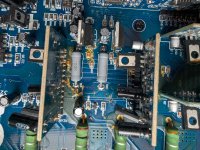
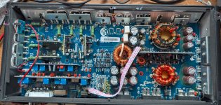
I have a Memphis PRXA700.5 that seems to be drawing too much current off the +/- 15V regulators and I cannot find the source. Backstory is the previous owner had a sub blow which he said took out the sub channel. When I got it, it was not in protection, but I found the sub channel had -45V DC on the sub output terminals. Checked all usual suspects with the transistors, but those tested OK. Turns out the 100 ohm series resistor that feeds the+15V regulator (7815) off of the +24V rail had blown open. I replaced both 100 ohm resistors on the +15V regulator and -15V regulator. This got rid of the DC on the subwoofer output terminal. The resistors still get very hot. The 7815 and 7915 regulators are not even getting enough input voltage to put out +15/-15V. After the drop across the resistors, the regulators are only getting about +/-12V at their input, so at the output it is between +/- 10.5-11V. Based on that, it would appear that the regulators are being asked for about 120mA ((24-12)/100) each. Does that seem normal? I would assume that current number is high since I do not get actual regulated +/-15V out, but I do not know what is normal. I could always just drop the 100ohm resistor value to get the regulated voltage, but I assume it was the value it was for a reason.

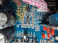
I get clean audio out of the 4 channel section. I also get audio out of the subwoofer section, but I feel the output is lower than what it should be. Using a thermal camera, nothing jumped out scorching hot besides the 100ohm resistors feeding the regulators. They are still within power rated spec, but they are still getting very hot. There were some warm spots on the power supply card, but nothing that instantly gave me concern. There is one section that I was assuming was part of the class D driver that has some suspicious things, but I can't be sure of it. There is a TL074C and LM358 that seem to have no power to them. I cannot easily say if it is part of the auto turn on or something else. I only say near the auto turn on section because it is right near that switch. The class D section does not seem to have a dedicated card like each of the other 4 full range channels do. I'm really at a loss if my issue is too much current draw "somewhere" or if I need to find out where those 2 IC's are supposed to be powered from. A schematic would be great, but any other guidance would be helpful also.


I get clean audio out of the 4 channel section. I also get audio out of the subwoofer section, but I feel the output is lower than what it should be. Using a thermal camera, nothing jumped out scorching hot besides the 100ohm resistors feeding the regulators. They are still within power rated spec, but they are still getting very hot. There were some warm spots on the power supply card, but nothing that instantly gave me concern. There is one section that I was assuming was part of the class D driver that has some suspicious things, but I can't be sure of it. There is a TL074C and LM358 that seem to have no power to them. I cannot easily say if it is part of the auto turn on or something else. I only say near the auto turn on section because it is right near that switch. The class D section does not seem to have a dedicated card like each of the other 4 full range channels do. I'm really at a loss if my issue is too much current draw "somewhere" or if I need to find out where those 2 IC's are supposed to be powered from. A schematic would be great, but any other guidance would be helpful also.


I've never seen this amp. One note is that there is a brown transistor (should be black) that was likely running hot. It may be OK but I think I'd check it carefully.
Strange things in the class D circuit?
Do you have power on the two mysterious ICs when you remove remote voltage?
Strange things in the class D circuit?
Do you have power on the two mysterious ICs when you remove remote voltage?
Where is the transistor you are seeing that is brown? Which picture of my post are you referring to?I've never seen this amp. One note is that there is a brown transistor (should be black) that was likely running hot. It may be OK but I think I'd check it carefully.
I was speculating that my issue with the TL074C and LM358 were part of the subwoofer circuit. I could be wrong as it isn't as apparent as the rest of the 4 channel items. It does appear they are part of the auto turn on circuit (see answer below).Strange things in the class D circuit?
The IC's themselves are not mysterious (TL074C and LM358) but their specific functionality was. When I removed remote voltage, they still remained unpowered. However, once I switched it to auto turn on (versus remote turn on), I got 30V on the Vdd pin of the TL074C, so I think that solves that. It still answer if the regulators are being overdriven, or they are meant to run lower that +/-15V. I'll work on doing an open load test on the subwoofer channel at least to see if it can drive to rail voltage on the output or not. I have to go find my test tones mp3 player again...Do you have power on the two mysterious ICs when you remove remote voltage?
I'll take a look in person closer to see if it was just the lighting on that one or if it really looks stressed.It's just in front of the SG3525.
No. In my first picture, the 7815 and 7915 are the TO220's right above the big 100 ohm through hole resistors. They are freestanding, not clamped. They also never seem to get hot right now. That makes sense though as they are only supplying ~100mA and have no voltage drop besides the internal voltage drop.Are the regulators clamped to the heatsink?
So I got the test tones out, and with a the gain on the amp maxed out, I was only getting 14V peak (10V RMS) with a 63Hz signal at the sub output terminals (unloaded). Certainly seems like I have reduced output there. The rails to the output transistor are sitting steady at +/- 45V. My only obvious symptom right now is the reduced regulator output. I could temporarily bypass the 100 ohm resistors to see if that brings the voltage back up and solves the issue temporarily, but that will have to be an adventure for tomorrow. It still does not tell me why it is being pulled down to begin with.I have to go find my test tones mp3 player again.
What was the input voltage driving the sub channel?
Direct input to the sub channel?
Sub crossover at highest frequency?
Does using the remote level control get the level up to clipping?
For the regulators, it wouldn't surprise me if it was poorly designed. It seems like they put the worst design engineers on the design of regulators since so many are so awful.
Only about 150mV at my in home setup. I can try it at work with a higher voltage function generator.What was the input voltage driving the sub channel?
Tried both direct to sub channel, and "combined" channels (meaning input into 2 channels, all amp outputs using the same channel). Same result for bothDirect input to the sub channel?
Yes,Sub crossover at highest frequency?
I don't have the remote level control, so unknownDoes using the remote level control get the level up to clipping?
It would be as simple as dropping the 100 ohm to a 47 ohm or so to get where it needed for +/- 15V output, just did not want to go there right away. LDO design is so simple that you might be right on the worst design engineers, but it is pretty hard to screw up...For the regulators, it wouldn't surprise me if it was poorly designed. It seems like they put the worst design engineers on the design of regulators since so many are so awful.
In the time I was working, I saw fewer than 5 remote controllers. 2 came with the same amplifier... and both were the wrong controller. When the controller was set to the lowest level, it would blow out the regulated supply. That had me scratching my head until I talked to the owner and he said he didn't know if they were the right controllers. They wen't. He found another one and it was OK.
If the amp was working as is, it shows how good the PS rejection ratio is for the op-amps. They have essentially no regulation if the supply wasn't sufficient for the regulators to reach their rated voltage.
For those who don't know what LDO is, it's a special regulator that requires lower headroom (input voltage that's above their rated output) to maintain their rated output. It's not generally a big difference but it can be important in some circuits.
So I went the cheap route at home because I didn't want to haul the amp to a different location. I found a headphone amp that I used to boost the original 100mv input signal to about a volt. I was able to get full output voltage on both the main channels (~17Vrms on a 25V rail) and sub channel (~32Vrms on a 45V rail). I then proceeded to hook up actual speakers and a sub and everything sounded good and worked as expected.
Saying that, I still do not like the non-regulated supply, so I am still going to go replace the 100 ohm resistors with 47 ohm resistors. If the current draw through the 100 ohm resistors can be trusted to stay the same, the 47 ohm resistors will drop about 5.5V (down to about 18.5V input into the regulator). That also means the regulator will be burning about ((18.5-15)*.12) = 0.42W. Per the datasheet, each regulator will have about a 30 degree rise which seems reasonable to me with these sitting in free air. I like that better than the resistors getting scorching hot. I'll report back after I get the new resistors in.
Saying that, I still do not like the non-regulated supply, so I am still going to go replace the 100 ohm resistors with 47 ohm resistors. If the current draw through the 100 ohm resistors can be trusted to stay the same, the 47 ohm resistors will drop about 5.5V (down to about 18.5V input into the regulator). That also means the regulator will be burning about ((18.5-15)*.12) = 0.42W. Per the datasheet, each regulator will have about a 30 degree rise which seems reasonable to me with these sitting in free air. I like that better than the resistors getting scorching hot. I'll report back after I get the new resistors in.
Clip-on heatsinks with heatsink compound will help reduce the temperature somewhat if they run hotter than you'd like.
Yea, I'll see what it ends up being once I get the resistor swapped. I'd rather have the regulator run a little warm with actual regulated voltages compared to a resistor burning hot and not even getting regulated voltages. I'll get the thermal camera on it once I swap.Clip-on heatsinks with heatsink compound will help reduce the temperature somewhat if they run hotter than you'd like.
I swapped out the 100 ohm resistors for 47 ohm 3W resistors. Resistors went from dissipating 1.5W to 1W. Input into the 15V regulators was 17.5V and the +/-15V regulators actually regulated as they were designed. Resistors get to about 80C in steady state, but this is fine for this design (and less than stock). The regulators themselves stayed under 60C, so there should be no issues there. Calculated dissipation for them was 0.375W, so no need for additional heatsinking. Ran the amp on all channels on my bench, and everything seems good. I'm going to call this repair a success.
- Home
- General Interest
- Car Audio
- Memphis PRXA700.5 Issues