Transistor matchers are not uncommon: in fact they are all over the place, and generally work satisfactorily. A good example has been presented recently by Mark:
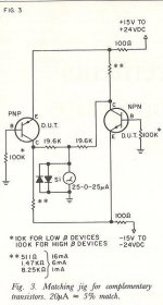
The vast majority however matches identical transistors. Complementary matchers are much rarer, and sometimes have issues:
It is possible to build something much better, whilst keeping things simple.
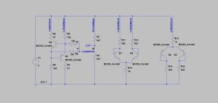
This matcher places the BE junctions in parallel, and biases them with two 1K resistors.
If the transistors have identical Vbe and Hfe, the circuit is perfectly balanced and the average voltage taken from the bases and emitters will sit exactly at mid-supply, and can be compared to a reference divider:

In this case, the complementarity is unperfect, the conduction of the P transistor is stronger, driving A negative wrt the reference divider.
Because of the exponential relationship between the delta-Vbe and the collector current, a tiny mismatch is easily detectable.
The Hfe of the transistors also affects the result, to a lesser degree.
You can convince yourself that the principle is sound:
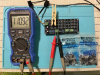
Here is the jig fitted with a synthetic transistor, a sex-changed BC547B into a BP547B:

As you can see, the match is perfect.
Here are some pics of the jig in action:


To be continued....
I handed out PCBs for this BJT Simple Matcher jig, during talk#3 at Burning Amp yesterday. For those who couldn't attend, I've attached the Gerber .zip file below. You can send it to a PCB fab and have some boards shipped straight to you.
If you haven't yet ordered PCBs from an online fab, it's fairly easy and painless. Here's a brief explanation: Ordering PCBs online (using Gerber files): A walkthrough -- featuring the fab "JLCPCB"
Unfortunately, some of the figures in my "slide deck" didn't render very sharply on the projection system, so I've included the entire...

The vast majority however matches identical transistors. Complementary matchers are much rarer, and sometimes have issues:
Hi All,
I've built the hi-fi headphone amp from Rod Elliott (project 113) and it sounds great (measures very well in LTSpice as well), however, I didn't get around to matching the BD139 and BD140 output transistors. I realise that it's probably unnecessary and doubtful that I'd ever hear a difference, but I decided it would be nice to do.
I found a thread (now closed) discussing this in which a matching circuit was offered by kct (I have attached the PDF here, I hope that's OK).
My question is that I have modelled this in LTSpice (attached), and whatever random transistors I pick, I...
It is possible to build something much better, whilst keeping things simple.
This matcher places the BE junctions in parallel, and biases them with two 1K resistors.
If the transistors have identical Vbe and Hfe, the circuit is perfectly balanced and the average voltage taken from the bases and emitters will sit exactly at mid-supply, and can be compared to a reference divider:
In this case, the complementarity is unperfect, the conduction of the P transistor is stronger, driving A negative wrt the reference divider.
Because of the exponential relationship between the delta-Vbe and the collector current, a tiny mismatch is easily detectable.
The Hfe of the transistors also affects the result, to a lesser degree.
You can convince yourself that the principle is sound:
Here is the jig fitted with a synthetic transistor, a sex-changed BC547B into a BP547B:
As you can see, the match is perfect.
Here are some pics of the jig in action:
To be continued....
Attachments
What performance can you expect from such a rudimentary jig?
Let's make some back of envelope calculations:
Suppose that for a given collector current, the delta-Vbe is 1mV.
From the junction equation we can infer that the delta-Ic will be Ic*Exp(1mV/26mV)=1.039-1=3.9% for both transistors.
Assuming they are near identical (which is our final goal anyway), the delta-Vbe will be split into equal variations of the Ic of both transistors, ie. 1.95% (they feed into one another).
Thus, in our case, where the voltage across the biassing/sensing resistors is ~4.2V (9V-0.6V)/2 it will change by 4.2*0.00195=81.9mV.
That's a simplification, because we have neglected secondary factors, and the fact that when the equilibrium is broken, one junction receives more current than the other, providing an implicit negative feedback.
However, if the transistors are closely matched, which is a starting assumption, the correction factors are small, and anyway we look for a match, not absolute values.
Thus, for a 1mV mismatch in Vbe, you can expect a 80mV reading (with a 9V supply), that is an 80X magnification compared to a plain vanilla test jig.
In addition, the Hfe is also taken into account, at a lesser level, which is also valuable since it intervenes in a good matching.
To be continued....
Question: In what cases (in audio amps) do we need to much N and P devices?
I always thought that output pairs (N/P) don't need to be matched. Is that right?
What about symmetrical VAS devices?
I always thought that output pairs (N/P) don't need to be matched. Is that right?
What about symmetrical VAS devices?
Yes and no: it depends on the specifics, but matching can generally reduce even order distortions.I always thought that output pairs (N/P) don't need to be matched. Is that right?
In a diamond-like structure, which can be used in some input circuits, matching eliminates unwanted offsets and similar issues
Practical considerations
1. Thermal aspects
As for any matcher, the thermal aspects are essential. Any temperature mismatch between the DUTs will ruin the matching, but it doesn't stop there: the whole test setup benefits from being isothermal.
Parasitic thermocouples, caused by the contact between the various materials like copper, brass, phosphor/bronze, kovar, etc cause error voltages if there are temperature gradients.
The best solution is to place everything in a hermetically closed box. The material doesn't really matter: metal or plastic work equally well.
Otherwise, you can use a simple cover: it is easier, but less effective.
If you use a breadboard, it is the best option: you plug a number of DUT's, 10 or 20, and you cover them, leaving the access contacts reachable, and you can test them all in sequence without having to wait or disturb anything.
Something to keep in mind is self-heating: with the values shown, the Vce is ~4V and the Ic is ~4mA resulting in 16mW dissipation, which is low but already sufficient to upset the measurement.
Each time you change or disturb something, you need to wait enough time to reach the thermal equilibrium, and we are not talking seconds but at least minutes or even more.
2. Tolerances
Indicative tolerances are appear on the schematic. They will result in a very accurate matching, but even if you use 1% throughout, the matcher will still operate satisfactorily for most applications: due to the operating principle, resistors mismatches cause small deviations, compared to DUT's mismatch which result in large deviations.
You can also hand-pick resistors with an ohmmeter.
Another option is to use a trimmer, like this:

Place the jumper X1, and adjust the trimmer to read 0 on the millivoltmeter.
3. Values
The values are indicative, and can be modified if the test current has to be changed: R1 and R2 determine the current. By lowering them, you can increase the test current at will, but remember that it will also increase self-heating effects.
Other values do not need to be altered, except if you want to seriously decrease the test current: in that case, it is advisable to increase R3 and R4.
If you want to increase the resilience to misconnections or faulty DUTs, you can insert a 47 ohm in each collector line.
The supply value is not critical, which is why the matcher includes no regulation, but the indication is proportional to the supply voltage, and if you need accurate absolute values rather than comparative ones, you should add a regulator
1. Thermal aspects
As for any matcher, the thermal aspects are essential. Any temperature mismatch between the DUTs will ruin the matching, but it doesn't stop there: the whole test setup benefits from being isothermal.
Parasitic thermocouples, caused by the contact between the various materials like copper, brass, phosphor/bronze, kovar, etc cause error voltages if there are temperature gradients.
The best solution is to place everything in a hermetically closed box. The material doesn't really matter: metal or plastic work equally well.
Otherwise, you can use a simple cover: it is easier, but less effective.
If you use a breadboard, it is the best option: you plug a number of DUT's, 10 or 20, and you cover them, leaving the access contacts reachable, and you can test them all in sequence without having to wait or disturb anything.
Something to keep in mind is self-heating: with the values shown, the Vce is ~4V and the Ic is ~4mA resulting in 16mW dissipation, which is low but already sufficient to upset the measurement.
Each time you change or disturb something, you need to wait enough time to reach the thermal equilibrium, and we are not talking seconds but at least minutes or even more.
2. Tolerances
Indicative tolerances are appear on the schematic. They will result in a very accurate matching, but even if you use 1% throughout, the matcher will still operate satisfactorily for most applications: due to the operating principle, resistors mismatches cause small deviations, compared to DUT's mismatch which result in large deviations.
You can also hand-pick resistors with an ohmmeter.
Another option is to use a trimmer, like this:
Place the jumper X1, and adjust the trimmer to read 0 on the millivoltmeter.
3. Values
The values are indicative, and can be modified if the test current has to be changed: R1 and R2 determine the current. By lowering them, you can increase the test current at will, but remember that it will also increase self-heating effects.
Other values do not need to be altered, except if you want to seriously decrease the test current: in that case, it is advisable to increase R3 and R4.
If you want to increase the resilience to misconnections or faulty DUTs, you can insert a 47 ohm in each collector line.
The supply value is not critical, which is why the matcher includes no regulation, but the indication is proportional to the supply voltage, and if you need accurate absolute values rather than comparative ones, you should add a regulator
Being fortunate enough to have an old boat-anchor Tek curve tracer, I'm pretty familiar with the thermal issues. Remember, once you deal with those in the test process, make sure you deal with them in the actual amplifier. It does little good to precisely match devices if they end up operating at different temperatures in the circuit!
Hi Elvee, thanks very much for this circuit. It does indeed work really well in LtSpice, and seems to work fine when built up on some veroboard. I used some sockets for the transistors so I can swap them easily. I was surprised by how long it takes to settle, minutes usually. I have also bee very surprised at the differences I'm getting between my BD139s and BD140s: over a volt in some cases and typically around 900 mV. I was expecting them to be much closer. I have of course checked my circuit with no devices installed and the voltages at each junction match LtSpice, so I don't think I've blundered.
Surely differences like that would make a noticeable difference in the actual amp - different gain for the positive and negative halves of the signal?
I have only tested about 20 of the 100 or so transistor combinations I have available, so hopefully I can find closer matches, but if not, should there be modifications to the amp to account for these differing gains?
900mV looks frightening, but remember that it is the magnified Vbe difference.Surely differences like that would make a noticeable difference in the actual amp - different gain for the positive and negative halves of the signal?
The actual difference would be 900/80=11mV: certainly not negligible, but not catastrophic either. For some circuits, it could be problematic, but others would tolerate it.
To answer your second question, you need to post the schematic to be specific enough
Thanks Elvee, that's helpful, I had forgotten about the multiplication factor. Attached is the schematic for the headphone amp (Rod Elliotts P113). I was thinking that perhaps R7 or R8 could be adjusted to account for the differences in the gains, but perhaps it's just not required?
Attachments
Note that this matcher, like most, matches mainly the Vbe, but the Hfe is also taken into account, to a lesser degree.
In your case, the Vbe is essentially unimportant: any mismatch will be compensated by a non-zero quiescent DC voltage at the output of the opamp due to the total DC feedback.
Paradoxically, the Hfe mismatch would have more influence: it would cause an asymmetry, causing some even-order distortion. This distortion will be mostly reduced by the loop gain, but the loop gain cannot be infinite and a (small) residue will inevitably remain.
I can try to design a matcher specifically intended for Hfe matching of complementary transistors, to ensure an ideal symmetry.
The chance of getting NPN to match PNP of a complementary pair from the same manufacturer is low and varies from batch to batch.
Ok to match in a complementary circuit if you are just looking for one or two pairs.
For larger matches (say 200 each), is it not more practical to measure Vbe and HFE for each device separately ?
Patrick
Ok to match in a complementary circuit if you are just looking for one or two pairs.
For larger matches (say 200 each), is it not more practical to measure Vbe and HFE for each device separately ?
Patrick
So, yes, I guess hFE is the more important factor here. I did fine the attached schematic here: https://www.biophysicslab.com/2021/04/27/testing_transistor_hfe/In your case, the Vbe is essentially unimportant: any mismatch will be compensated by a non-zero quiescent DC voltage at the output of the opamp due to the total DC feedback.
Attachments

It doesn't look very convenient for matching only.So, yes, I guess hFE is the more important factor here. I did fine the attached schematic here: https://www.biophysicslab.com/2021/04/27/testing_transistor_hfe/
This would be easier:
I have shown a BC847C instead of a BC547B, because the gains match much better.
The test current is 1mA, but it depends on the Hfe, and can easily be adapted by using another value for R1. The 33 ohm protection resistors might need to be adapted for much higher currents.
The switch is a center-off type, but if you want to always use the highest sensitivity, you can dispense with it completely and get rid of R4, 5 and 8.
That way, the sensitivity will be limited by just the Early effect of TUTs.
Attachments
Some applications require mostly Vbe matching, others Hfe matching and critical ones require both. In this case, the test could be made in two passes: one for the Vbe, and one for the Hfe, on the group of devices matching well for VbeFor larger matches (say 200 each), is it not more practical to measure Vbe and HFE for each device separately ?
Thanks everyone for your help with this project! In the end, I used the Simple Jig from https://www.biophysicslab.com/2021/04/27/testing_transistor_hfe/ (attached) to measure hFE for each transistor (which was pretty quick and easy), then used the original matcher to pick the best matches from those with closest hFE.
The transistors were all pretty close - I had bought the BD139/140-16s so they should have been similar, but the ranges I got were 106.11 to 106.33 for the PNPs and 105.69 to 105.85 for the NPNs.
The transistors were all pretty close - I had bought the BD139/140-16s so they should have been similar, but the ranges I got were 106.11 to 106.33 for the PNPs and 105.69 to 105.85 for the NPNs.
Attachments
It looks OK, and the magnification factor for 5V is indeed ~40. The figure is not completely accurate of course, because of the simplified calculation I made and other secondary effects, but for matching the approximation is perfectly sufficient.
Note that I have also described a matcher for same sex transistors, also benefiting from a similar magnification mechanism. If your multimeter has a sufficient resolution, you don't really require it, but it has the side advantage of reducing thermoelectric pollution from the jig to multimeter interface
Note that I have also described a matcher for same sex transistors, also benefiting from a similar magnification mechanism. If your multimeter has a sufficient resolution, you don't really require it, but it has the side advantage of reducing thermoelectric pollution from the jig to multimeter interface
- Home
- Amplifiers
- Solid State
- An original, high-performance complementary transistors matcher