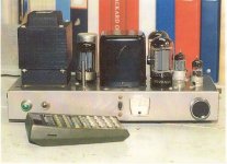
Hi all, I'm going to breathe new life into a Heathkit W4-AM amplifier, that my Dad built in the late '50s. At some point in the past, and for reasons Dad can't quite recall, the original power transformer was replaced. The new Hammond (274BX) is similarly spec'ed to the OEM, just slightly lower HV at 375/0/375 vs the original 380/0/380. However, Dad noted on the schematic, along with the new transformer specs, that he changed the rectifier tube from a 5V4G to a 5U4G. No idea why... Given that the 5V4G draws less heater current, and has a lower forward voltage drop, would I be better to revert back? or is the higher current capability of the 5U4G going to make the amp more reliable? If you're not too familiar with this amp, it uses a pair of 6SN7's for the gain stage and phase splitter, followed by a pair of 5881's for the power stage. I won't be making use of the pre-amp power output capabilities (have a Mesa Studio for that task!). Appreciate any thoughts or suggestions!
Cheers, Dave
Cheers, Dave
Maybe it was an attempt to lower B+ a bit. Possibly the output tubes were right at the dissipation limit using the Hammond?
Probably a good idea to replace the multi can cap & the two 20uf caps for the power supply, given their age.
jeff
Probably a good idea to replace the multi can cap & the two 20uf caps for the power supply, given their age.
jeff
Last edited:
Thanks Jeff! I would have thought the Hammond would have reduced the B+ already, after all, it's 5 volts lower than the OEM transformer (although maybe the current capability is higher?). In any event, a slightly lower B+, and the corresponding lower power, would be insignificant to me, which is part of the reason I'm leaning towards using the 5U5G variant (although the higher heater load is a little concerning).... also, I am planning on replacing all the electrolytics, given they're 60+ years old!
The original power transformer was probably replaced because they had a tendency to fail. The amp was intended to use the 5V4 and it's the better tube for this amp. Definitely replace the stacked input caps and the can cap. I would highly recommend an Authenticap. They are well-made and have a surge rating of 600VDC. Avoid CE can caps, they have a tendency to arc when pushed anywhere near their voltage rating. The 5V4 technically has a "slow" warm-up but it's not as slow as one would hope, so the caps will see around 500VDC for 5 seconds or so before the other tubes warm up.
You should read this article from Audiokarma. The mods will greatly improve the performance and stability of the W4.
https://audiokarma.org/forums/index.php?threads/heathkit-w4-am-modifications.459630/

You should read this article from Audiokarma. The mods will greatly improve the performance and stability of the W4.
https://audiokarma.org/forums/index.php?threads/heathkit-w4-am-modifications.459630/
Last edited:

One thing that is not included in Dave Gillespie's mods is a pair of current-measuring resistors. You should add two 10 ohm 1/2 watt resistors between the two test jacks and the "top" of the 360 ohm cathode resistor. This allows you to place a standard ohmmeter across the test points and balance the output tubes. You adjust the balance pot until it's as close to 0 millivolts as possible.

PS. You could also use a 5AR4 rectifier, get a nice slow turn-on and a bit more B+. Put some Gold Lion KT66s in there and you will have a really lovely Williamson.
I read somewhere the older ones ran a bit high, because they were wound for 115v mains, and many people are getting much higher mains voltage compared to back in the day.I would have thought the Hammond would have reduced the B+ already, after all, it's 5 volts lower than the OEM transformer
You'll soon know once you get the amp up and running.
jeff
The newer Hammond 200 series all have 120VAC primaries. If this one is older, it may only have 115VAC primaries. If that's the case, a CL-80 thermistor on the AC input will drop a few volts and also reduce the filament surge.
I don't see a 4x 20uf cap in their catalogue, so I'm curious what you used. The one listed for the Dynaco ST70?I would highly recommend an Authenticap.
jeff
This one:
https://vacuumtubevalues.com/produc...urge-twist-lock-capacitor-authenticap-ktl-13/
Use the 30uF section after the choke. It's perfectly fine to do that.
https://vacuumtubevalues.com/produc...urge-twist-lock-capacitor-authenticap-ktl-13/
Use the 30uF section after the choke. It's perfectly fine to do that.
You can also use a 10uF/600VDC film cap in place of the two stacked input caps. A Solen works nicely here, or Cornell-Dubilier. Just be sure you use a bleeder resistor across it, like 200K/5 watts.
The great thing about this modded circuit is that it changes the W4 from a just-okay "budget" tube amp to a highly-competitive one. ;-) You may want to snag a second one from eBay and build yourself a matched pair. It's a very beautiful 20 watts.
Some reading to do here! Many thanks "GG" & "Kid" this is exactly what I was hoping for! Cheers, Dave
You should read this article from Audiokarma. The mods will greatly improve the performance and stability of the W4.
If OP Dave could live with fewer but better watts he should also consider Dave Gillespie’s latest magic with the Trioded W4-AM. See here:
https://audiokarma.org/forums/index.php?threads/new-build-gillespie-w4am-triode.1069684/
About 1960 I built myself a pair of PP UL 6L6GC amps, the PT is a Hammond 273BX.
17 yrs later I parked the pair on the shelf, I'd bought a Sansui AU7i7/TU717 setup.
I found replacement 6L6GCs were under stress, they were not as sturdy as the originals.
More recently, power in general is a few volts higher on line.
Problems, Problems!
17 yrs later I parked the pair on the shelf, I'd bought a Sansui AU7i7/TU717 setup.
I found replacement 6L6GCs were under stress, they were not as sturdy as the originals.
More recently, power in general is a few volts higher on line.
Problems, Problems!
Attachments
I'm thinking oval motor run. Might just fit. 🙂You can also use a 10uF/600VDC film cap in place of the two stacked input caps.
That's exactly what I did, but that was many years ago when our dollar was worth something, and shipping was about half what it is now. I bought one from the US, as I couldn't find another single one up here at the time.You may want to snag a second one from eBay and build yourself a matched pair.
jeff
Dave, the devil can be in the technical detail - so some caution may be advisable.
Although the 274BX may appear equivalent, it would be wise to check its influence on the valve rectifier's peak current capabilities. That is a technical effort needing measurement of transformer winding resistances, and a simulation app like PSUD2. It may be that the 274BX winding resistances are noticeably different than the original. The 5U4 has a higher capability for peak operating currents than the 5V4, but as indicated it may add turn-on stress to all the filter and coupling caps in the amp, which is another technical effort to assess.
There is also the initial query about why the power transformer was replaced. Likely reason is that it failed due to either a rectifier fault or a high load current related fault (many plausible reasons including filter capacitor failure, output valve failure or bias/leakage related stress, accidental wiring short). It may be in your interest to improve the B+ power supply related protection (aka "bullet proofing") by adding a secondary winding CT fuse, and adding series ss diode protection to each rectifier anode.
Ok, first off, thanks to everyone for posting, lots to read and think about, and I appreciate it! I'm good with solid state, but tubes are not my forte....
And secondly, thanks for the upgrade suggestions. I'll definitely look into those as I progress towards getting this beast operational again. FYI, this amp was working when retired, and the power transformer change was done many years before it was retired (at least 10).
Now, the Hammond transformer: No tubes installed, my variac set to 120 vac on the primary, I'm reading 405 on the HV secondaries. This is with no load, but still higher than I would have thought for a 375 volt spec. This may be the reason for the 5U4 change. I'll see what I can find for a load resistor around here, to gauge the transformers output impedance, and where things might settle with the rectifier tube in place.
Bullet proofing: Interestingly, Dad has already installed a fuse on the HV Center Tap! He wasn't really an electronics guy, but someone gave him some good advice.
The electrolytic caps: As I mentioned, I was planning on replacing them all (after 60+ years). Other than covering up the chassis hole is there any advantage to using the original multi-cap style unit as you suggested GG? I've seen 22uFd 500v Caps for about $4.00, so $16 plus a couple of terminal strips, vs $65....
Cheers, Dave
Sounds like you're off to a good start! Regarding the can cap, the Authenticap is a very good capacitor and will tolerate any over-voltage at turn-on. This can exceed 500VDC. Plus, it preserves the original look. Don't cheap out, you don't want to have any problems or have to rebuild it 5 years from now. ;-) But if you go with individual caps, be sure you get 105 degree rated ones. Rubycon makes compact, 600VDC 105 degree snap-in caps you can get from Digikey.
For the Hammond, sounds like it's a 115VAC primary. Again a CL-80 should drop the line voltage by a few volts and also prevent current surges to the filaments, etc. That and the load should bring it down pretty close to the original. The turn-on surges were what borked a lot of these Heathkit amps.
In terms of B+, the circuit is not that fussy. I've built about a dozen Williamsons using this same circuit and I typically shoot for 430VDC at the OPT center tap. With the transformer losses and minus the bias voltage of 38-40VDC, you get less than 390VDC on the plates, which will not stress the 5881s. Heathkit ran them quite low, less than 50mA each. The total cathode resistance including the balance resistors and pots is about 420 ohms, so they are not running very hard. So anywhere between 400VDC and 430VDC for B+ is fine.
- Home
- Amplifiers
- Tubes / Valves
- Restoring a Heathkit W4-AM: Rectifier tube question