Use of the LC filter indeed makes more sense than cheap LDOs in this case. Although there are modern LDOs with higher bandwidth, like tps7a47, they still do not provide enough PSRR at high voltage (15-20V) output in the DC-DC operating frequency range.
But somehow I do not feel comfortable with proposed LC values, 2.2mH and 31 Ohm is too much. I'd rather use 2.2uH/220uF + some small MLCC.
But somehow I do not feel comfortable with proposed LC values, 2.2mH and 31 Ohm is too much. I'd rather use 2.2uH/220uF + some small MLCC.
There are many possible choices for component values in LCR filters optimized for the correct quality factor "Q" , @eclipsevl . For example,
PO89ZB on these Forums uses (2.2 microHenrys + 0.04 Ohms + 470 microFarads)
AmyAlice on these Forums uses (10 microHenrys + 0.10 Ohms + 470 microFarads + 1.0 microFarad RF Feedthrough capacitor, P/N YFF31HC2A105MT000N by TDK)
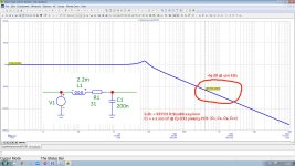
One way to explore the performance characteristics of the filter linked in post #1 above, it to examine its behavior in circuit simulation. Perhaps using LTSPICE or QSPICE
PO89ZB on these Forums uses (2.2 microHenrys + 0.04 Ohms + 470 microFarads)
AmyAlice on these Forums uses (10 microHenrys + 0.10 Ohms + 470 microFarads + 1.0 microFarad RF Feedthrough capacitor, P/N YFF31HC2A105MT000N by TDK)
One way to explore the performance characteristics of the filter linked in post #1 above, it to examine its behavior in circuit simulation. Perhaps using LTSPICE or QSPICE

Of course 🙂There are many possible choices for component values in LCR filters
Out of all examples you listed the series resistance of the inductors is in range of 10s-100s of milliohms, whereas in the post #1 it is 31 Ohm. That was my main point, one should not only consider AC performance of the filter but also overall output impedance of the power supply.
There are many possible choices for component values in LCR filters optimized for the correct quality factor "Q" ,
One way to explore the performance characteristics of the filter linked in post #1 above, it to examine its behavior in circuit simulation. Perhaps using LTSPICE or QSPICE
I use a Microcap 12 simulator, see attached results
Attachments
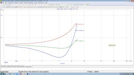
Just run a transient simulation of the phono amp with such filter and you'll see that because of the inductor resistance there will be couple of mV ripple at the amplifier power rails (green waveform, ~3.2mV ripple correlated with input signal).I use a Microcap 12 simulator, see attached results
In the video input is shorted so it is a steady-state case.
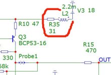
To measure the PSRR, you must apply the "input" signal not to the phono preamplifier input (there is no 400 kHz there), but in series with the +18 power source, in addition, to the left of the resistor R23, you must include a grounded blocking capacitor of 0.2 uF, as is in my filter circuit and phono preamp PCB.Just run a transient simulation of the phono amp with such filter and you'll see
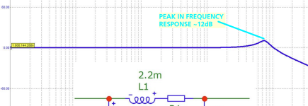
This peak is at 7 kHz, which is too high for 50 Hz and too low for 400 kHz.peak
This is not a PSRR simulation.To measure the PSRR, you must apply the "input" signal not to the phono preamplifier input (there is no 400 kHz there), but in series with the +18 power source
Yes, I have it.in addition, to the left of the resistor R23, you must include a grounded blocking capacitor of 0.2 uF, as is in my filter circuit and phono preamp PCB.
The simulation shows that due to IR drop on R23, there will be ripple on the amplifier power rails. The frequency of input signal at the waveforms above is 1kHz.
Perhaps you assume that current consumption of the phono stage is constant regardless of the input signal but it is not. So power rails effectively modulated by the input signal with such high impedance power source.
3 mV rails ripple with 300 mV Vout is only 1%. It does not affect either the frequency response, THD, or SNR of preamp.power rails effectively modulated by the input signal with such high impedance power source.
Agreed.3 mV rails ripple with 300 mV Vout is only 1%. It does not affect either the frequency response, THD, or SNR of preamp.
And heading for 10uV supply voltage ripple is useless either.
it is as useless as "90 uV output noise voltage" in LM78L15 datasheet ;-)heading for 10uV supply voltage ripple is useless either
That was my main point, one should not only consider AC performance of the filter but also overall output impedance of the power supply.
The simulation shows that due to IR drop on R23 (in my simulation it is R35) THD even decreases - see attached dataThe simulation shows that due to IR drop on R23, there will be ripple on the amplifier power rails. The frequency of input signal at the waveforms above is 1kHz.
Attachments

Last edited:
- Home
- Amplifiers
- Power Supplies
- Transformerless very low ripple <10 uV PS +-18 V 50 mA for top quality phono preamp