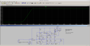
I've been playing around with some variations on the old JLH auto bias scheme. The latest version is shown below, with a plot of the idle current vs. time. The nice part about this scheme is that it permits fairly precise control over the idle current:

Looking at the positive side of the amplifier, the relevant portions are Q1, Q2, Q7 and Q9. Q5 is your usual driver transistor. Q1 is the primary power-output device and Q2 serves a dual role of setting the idle current "gain factor" and idle current sensing. R1 and R23 establish the ratio of sense current vs. primary idle current (allthough it contributes a fraction of the idle current as well). R22 and Q9 sense the idle current through Q2, so R22 sets the actual idle current.
My first iterations on this autiobias variant placed a 100uf capacitor between Vcc and the base of Q9), but the idle current took a VERY long time to settle, exhibiting a huge overshoot in the idle current. It took me awhile to figure out that it and C1 were acting in the idle-current feedback loop so it had really terrible gain margin. I was concerned that omitting the capacitor would have an adverse effect on the amplifier's frequency response or distortion because it might permit a large modulation of the idle current due to the signal, but simulations didn't support that theory. The idle current control loop is stable and has no overshoot w/o that capacitor.
Here's a screenshot showing an FFT of a 1KHz 10Vpp signal:

I don't believe a physical realization of this circuit would come close to THIS performance but it is an encouraging result.
For "'the real deal" I would add bootstraps to the sense transistors so the amp's output could swing closer to the rails w/o disturbing the idle current. The main output transistors would need to be beefier than the ones in my simulation, too.
On the principle of "there's nothing new under the sun", I'd be interested to learn if I'm following a path that's already been taken.
On a different note, I can't get LTspice to perform an AC sweep on this circuit. Possibly because it takes ~80ms for it to settle??? I tried using savebias/loadbias but that doesn't work, contrary to one article I found online. It would be really nice to know what its gain/phase margin is.....
Looking at the positive side of the amplifier, the relevant portions are Q1, Q2, Q7 and Q9. Q5 is your usual driver transistor. Q1 is the primary power-output device and Q2 serves a dual role of setting the idle current "gain factor" and idle current sensing. R1 and R23 establish the ratio of sense current vs. primary idle current (allthough it contributes a fraction of the idle current as well). R22 and Q9 sense the idle current through Q2, so R22 sets the actual idle current.
My first iterations on this autiobias variant placed a 100uf capacitor between Vcc and the base of Q9), but the idle current took a VERY long time to settle, exhibiting a huge overshoot in the idle current. It took me awhile to figure out that it and C1 were acting in the idle-current feedback loop so it had really terrible gain margin. I was concerned that omitting the capacitor would have an adverse effect on the amplifier's frequency response or distortion because it might permit a large modulation of the idle current due to the signal, but simulations didn't support that theory. The idle current control loop is stable and has no overshoot w/o that capacitor.
Here's a screenshot showing an FFT of a 1KHz 10Vpp signal:
I don't believe a physical realization of this circuit would come close to THIS performance but it is an encouraging result.
For "'the real deal" I would add bootstraps to the sense transistors so the amp's output could swing closer to the rails w/o disturbing the idle current. The main output transistors would need to be beefier than the ones in my simulation, too.
On the principle of "there's nothing new under the sun", I'd be interested to learn if I'm following a path that's already been taken.
On a different note, I can't get LTspice to perform an AC sweep on this circuit. Possibly because it takes ~80ms for it to settle??? I tried using savebias/loadbias but that doesn't work, contrary to one article I found online. It would be really nice to know what its gain/phase margin is.....
Attachments
Douglas Self published a class-A amplifier with bias control loop in the mid-1990's in Wireless World, or Electronics and Wireless World or whatever it was called then. I don't remember the details of his implementation.
Why don't you drive Q7 and its PNP colleague directly (possibly with a resistor to avoid excessive transient currents) from the voltage across the emitter resistors of Q1 and its PNP colleague?
There is also this, but I never built it: https://www.diyaudio.com/community/...ether-it-works-in-a-or-ab.308636/post-5098895
That's the first thing I tried but the circuit didn't behave well. I speculate that the effective "common mode rejection" wasn't good enough. The design I show above does a better job of separating the current and voltage signals. It also is easier to set the actual idle current with this one, since it has two separate "knobs" to tweak. One is the current ratio and the other is the setpoint.Why don't you drive Q7 and its PNP colleague directly (possibly with a resistor to avoid excessive transient currents) from the voltage across the emitter resistors of Q1 and its PNP colleague?
I may go back to version 1, now that I've figured out a few oddities with the way LTSpice reports node voltages. Apparently if Newton's method fails to find the initial operating points the node voltages that pop up aren't accurate, that really confounded me for awhile -- some of the voltages/currents were just plain screwy.
Thank you for the references. There also are some very recent threads that use some form of feedback to accomplish much the same thing. The MF A1 comes to mind....
BTW I was able to get LTSpice to perform AC sweeps by adding some initial voltage values to the coupling capacitors. Sweeps showed that the circuit has very good phase and gain margins

I forgot to write 'with Q7's and Q8's emitters only connected to each other', but looking at the schematic and your latest post, I guess that's what you tried first.
It's a variant of something I have used since 1994 for a class-AB amplifier, see
"Audio power with a new loop", Electronics World February 1996, pages 140...143, https://worldradiohistory.com/UK/Wireless-World/90s/Electronics-World-1996-02-S-OCR.pdf
"Audio power with a new loop", Electronics World February 1996, pages 140...143, https://worldradiohistory.com/UK/Wireless-World/90s/Electronics-World-1996-02-S-OCR.pdf
I was able to get the version that uses voltages tapped off the emitter resistors but it is more difficult to set the idle current. I found it necessary to tweak the current ratios using base stopper resistors on the main output transistors. That's because the emitter voltage on the "sense" transistor always has to be equal to Q7's EB voltage, so there's not much leeway in setting the current ratios. The scheme shown in my OP isn't affected by that requirement, so no base stoppers are needed.
Yes, that approach is better than my old scheme since it samples the current through both output devices. I sampled the current on the PNP collector side to address concerns I had regarding modulating the sensed current via the sense transistor's early voltage, but stopped short of sensing the current on both output devices. I belatedly discovered that was desirable......It's a variant of something I have used since 1994 for a class-AB amplifier, see
"Audio power with a new loop", Electronics World February 1996, pages 140...143, https://worldradiohistory.com/UK/Wireless-World/90s/Electronics-World-1996-02-S-OCR.pdf
- Home
- Amplifiers
- Solid State
- Closed loop control of class A idle current