Having just recently completed the Cordell upgrade on my DH-220, I completely agree with your assessment!If you're going to take it apart, go full-on and install a modified circuit. I built the Cordell project and it is chronicled here:
https://www.diyaudio.com/community/threads/hafler-dh-220-taking-apart-a-perfectly-good-amp.407907/
It completely transformed the amp from a sleepy old 1980s relic (albeit a pretty good sounding relic) into a completely new experience.
I have nothing but good things to say about the change in sound quality, and in particular the transient response and imaging is far superior to the original.
I went a different route on my DH-200, the Qua-co PC1-b boards, 35 amp rectifier, 18K PSU filter caps, 15A switch, gold plated RCA's and binding posts, Qua-co Speaker protect module blah, blah,blah.
I have an important question to ask you all. The DH-200, with or without this upgrade appears to have no chassis ground, everything appears to be floating. The only thing that appears to be grounded are the 0.1 mf PP caps on the OPS Mosfets.
What precautions should I be taking to inject a signal and read on a scope? Isolation transformer for the Amp and Test equipment? 3-2 AC adaptors for the amp and test equipment? I don't have a hand held scope or Sig Gen and really don't want to blow up anything.
I'm looking getting this combo oscope/function generator. It is not USB powered.
https://www.amazon.com/Hantek-Oscil...-1-spons&sp_csd=d2lkZ2V0TmFtZT1zcF9hdGY&psc=1
Thanks,
Lonnie
Last edited:
I guess that' s the best you can encounter, as floating signal ground for sure avoids ground loops.
Best regards!
Best regards!
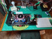
Update on the DH-200 Qua-Co build. Everything went fine, instructions are terrific, build went as planned......until
Brought the amp up, set the bias and dc offset without issue. While testing with a 1k sine input it blew the 3A speaker fuse just as it reached clipping. Of course it did, the Qua-Co boards allow for higher RMS output. Changed to 4A speaker fuse and clipping tests went as planned. 161 watts RMS just below clipping. Played nice on expendable bench speakers for a few hours.
Before integrated into my system I thought it wise to check the bias and offset one last time before installing the cover. That's when I descovered that DC offset pot on the channel that had blown the 3A speaker no longer worked correctly. Turning it in either direction would only change the DC offset for a split second and then the value would return to 6-8mv. I know that's a very low DC offset value but I can't in good conscience allow the pot to remain nonfunctional.
I contacted the Qua-co seller (Ed Fantasia) and he recommended some likely defective components to check. They tested good, so I tested ALL the components on board and found nothing wrong with any of them. I contacted Ed again, informed him of my component test procedures and equipment used (one of them being a cheap Fnirsi component checker), and he replied, "Don't worry, I'll send you a complete semiconductor kit for that board at NO CHARGE". How's that for customer service?
I have read that its easy to draw false conclusions using cheapo component testers to test semiconductors; that the device may test good but fail at higher voltages. I guess I'm not living the dream.😒
Attachments
Having just recently completed the Cordell upgrade on my DH-220, I completely agree with your assessment!
Any more sonic evaluation since running it in the big boy room?
So, I never did figure out which component was causing the DC offset problem with the Fantasia/QuaCo PC-1b board, but the bag of semiconductors Ed sent for free fixed the problem. Been running the "Utlimate Audiophile Upgrade" DH-200 for a few days now. Sounds great. Truly a night and day improvement over my other DH-200 with only an ecap refresh.
I'm not an audiophile, so I won't attempt to write an article with all the fancy phrases and catch words. Firstly, the amp is very quiet. A very faint hum can be heard from both channels only by placing the ear within 1 inch of the driver. Most notably, the upgrade improved the extended bass response with much more control and provides smoother mids, especially upper mids. Female vocals and horns sound lifelike with no harsh overtones. The dynamic range is also improved, offering fine low level recording detail to "blow your head off" when the recording offers it. It's a treat to listen to for hours on end without feeling drained. That's saying a lot because the NHT 2.9 tweeters are a bit hot. The upgrades brought the power output from 114W rms to 167W rms before clipping.
I'm very happy with the QuaCo upgrade and feel it's a fun project and a great bargain. I may try the Cordell upgrade on my other 200 just for the experience, as I have doubts that I would hear any sonic improvements.
Lonnie
After sitting on these boards and factory matched exicons for some years now, my experience listening to my tastefully upgraded 9180 has my really inspired to make this build a reality. Fun stuff..


I am curious if anyone (re)building these amps has experienced any instabilities that have/might be attributed to differences between Exicon vs. Hitachi/Renesas Lateral power MOSFETs? Or even different pairs of Hitachi/Renesas Lateral pairs like the 2SK1058+2SJ162 pair vs. 2SK2221+2SJ352 pair? 2SK1058/2SJ162 look to have slightly different characteristics as compared to 2SK2221/2SJ352.
Maybe Rick or Bob did some additional experimentation for this project and could comment?
What stimulated the question is reading through comments on the experiences from folks who built Damir's 120W CFA amp using Exicons while Damir based his design and builds upon Hitachi/Renesas devices.
Maybe Rick or Bob did some additional experimentation for this project and could comment?
What stimulated the question is reading through comments on the experiences from folks who built Damir's 120W CFA amp using Exicons while Damir based his design and builds upon Hitachi/Renesas devices.
Last edited:
@pwayland, I see you are stuffing those brown Dales in where there should be SFR16S or MF0204 or MBB0204.
Above mini types are as precision as you need. A lot of SFR16S are being EOL so use the others mentioned above.
The pcb is tight enough as it is 🙂 Suggest to stuff resistors first, solder, then the rest because it's a mess of leads other wise.
Dale has been thinning the heard on those brown guys lately as well.
As for Exicon vs Hitachi, all I know is Bob used original Hitachi in his builds and I used the Exicons to try them out to be sure they worked in our case.
No other comparisions were made. I guess I could try out the dual die parts since I have some.
I like those brown body Dales because the values are printed on the bodies.
PRP and Holco also print values on the bodies. Are the PRPs acceptable substitutes to the MBB0204?
PRP and Holco also print values on the bodies. Are the PRPs acceptable substitutes to the MBB0204?
I think the PRP and Holco 1/4W equivalents are both physically longer than the NF0294 or the MBA0204. But I think they can be fitted with creative lead bending, but with added inductance, I guess.
Rick, I appreciate your thoughtful response and it was early days when I started stuffing those boards. I kept your mailer for date reference... Are they worth pulling? I don't think so, but maybe. I rework all the time. I'll have many more questions. So glad you noticed my interest in this project. I have a fair amount of knowledge and Jim , 6L6 and I share an ear in CO. I'm getting excited about making monoblocks with the 6 pairs of exicons connected to a rails with really low impedance power supply direct DC LiFePO4. But the zfoil load takman to ground shut attenuator in front of iron pre SUSY>X150.5...... Dunlavy heaven. Is blowing my mind so, peace.. PS hope to promote what I see as a really wonderful gem in the old hafler fan world..I often promote In my hafler groups. Aside from my praise for Jim Strickland. Peace 🙏 PS, PS what do you think about the floating Trans PS?@pwayland, I see you are stuffing those brown Dales in where there should be SFR16S or MF0204 or MBB0204.
Above mini types are as precision as you need. A lot of SFR16S are being EOL so use the others mentioned above.
The pcb is tight enough as it is 🙂 Suggest to stuff resistors first, solder, then the rest because it's a mess of leads other wise.
Dale has been thinning the heard on those brown guys lately as well.
As for Exicon vs Hitachi, all I know is Bob used original Hitachi in his builds and I used the Exicons to try them out to be sure they worked in our case.
No other comparisions were made. I guess I could try out the dual die parts since I have some.
Last edited:
In the case of DH500, I saw some changes on windings of L1.....I count 13 windings on a picture....
There are the same number of windings (11) ? .. ...with 14-16 awg and internal diameter is...?
Thanks in advance.
There are the same number of windings (11) ? .. ...with 14-16 awg and internal diameter is...?
Thanks in advance.
Slowly but surely making progress. finally developed a good method of work solder surface mount melf resistors using lead trims. R4,R5,R7,R8. I didn't see discussion to alternative dc blocker caps C5, C6 in the build guide, however alts in the BOM. Is the circuit stable without?


R4 and R7 mounted from underneath
R4 and R7 mounted from underneath
Why the bypass across C5? It buys you zero. I'm also trying to figure out why you simply don't used leaded parts instead of MELFs and adding leads. Again, doesn't buy you anything.
Agreed. Use leaded through-hole resistors. It will simplify your life and will improve reliability in the long run. Also, many MELFs are inductive. It may be meaningless here but maybe not depending on the location.
Also, why do you seek an alternative for the capacitors? Is it because you can't get the specified component?
The circuit shows a 10 uF electrolytic bypassed with a 1 uF polyester type.
Would you prefer a polypropylene cap instead of the specified polyester?
Also, why do you seek an alternative for the capacitors? Is it because you can't get the specified component?
The circuit shows a 10 uF electrolytic bypassed with a 1 uF polyester type.
Would you prefer a polypropylene cap instead of the specified polyester?
Last edited:
It’s called a dual footprint so you have stuffing options to use one or the other or both. I’ve seen some short them out and go in direct.
Same goes with jfets, there is a footprint for sot23-6 on the back or use the through hole dip-6 for a socket/carrier or direct solder.
In the ? about the coil, it really does not matter if it’s 10,11,12 turns, that does come down to the wire gauge you use and the available space to place it. 18awg is okay for the Dh-220 but suggest to use 16,17, 1.2mm for a dh-500.
The op is going way off script as it is with the proposed ops. and use Melfs with leads soldered is just making it a more difficult assembly as if it isn’t already.
Last edited:
- Home
- Amplifiers
- Solid State
- Hafler DH-200/220 Mods