I'm working on (have had it WAY longer than expected) an Epicure M1 power amp from the early 70s. A local audio enthusiast dropped it off over the summer for me to look at and restore as necessary (I had fixed a Mitsubishi DA-A15 for him a couple months prior). He realizes I'm just a hobbyist, and has told me to take as much time as necessary, but this is dragging out much longer than I expected. And since there's next to no documentation on this amp, I'm somewhat flying blind. What I mean by that is, I have a schematic, but it lists no expected voltages, part values, wattages, etc. The amp boards aren't marked either. The L channel bias is giving me fits, as in, it won't really adjust much whilst adjusting the trimmer. The R side adjusts smoothly and starts changing immediately as the trimmer is adjusted. So as not to rehash the whole process and work done, I'm linking the restoration thread I started over on AK (I hope that's ok).
The original plan was to just replace defective parts with new, which was going fine until I ran into the bias issue (again, all explained in the AK thread). Due to what I found as component testing occurred, all the transistors have now been replaced on both boards with the closest modern subs I could find, and while that could be the source of the problem, I would think the issue would be occurring with both channels, not just one, so something else MUST be going on that I haven't found yet. My last post on AK has a voltage chart that I created by powering up one channel at a time and probing all the transistors. HOWEVER, without expected voltages, I can't be sure either channel is really working as it should.
The owner recently picked up another one of these amps and is willing to drop it off for me to take measurements from, and I may be at that point, but I'll still not be sure if it's really functioning properly other than it plays music.
So, any and all thoughts/suggestions on what to look for or try differently are welcome. Thanks in advance....
John
I think it's best to post at least the schematic here.
I for one don't have an AK account so I can't see them over there.
Edit: The voltage chart would be nice too.
I for one don't have an AK account so I can't see them over there.
Edit: The voltage chart would be nice too.
I'll leave it to others to make sound proposals.The L channel bias is giving me fits, as in, it won't really adjust much whilst adjusting the trimmer.
In all good faith, why oh why did you replace all these transistors? I know this question doesn't help much but this way of repairing is really asking for trouble. 🙂

Due to what I found as component testing occurred, all the transistors have now been replaced on both boards with the closest modern subs I could find, and while that could be the source of the problem
That opens a whole can of worms because slightly different characteristics can certainly put things like bias adjustment out of range and worse can cause instability and oscillation due to differing high frequency performance to the originals.
If the bias adjusts but jumps around then that is a sign of instability.
If the bias current is zero and will not increase then you need to begin by measuring the voltage across the vbe multiplier and noting what voltages you see at each end of the presets range. You can compare that to the other channel and the expected target value would be around 2.5 volts to begin to see an increase in bias current.
I assume the DC offset is close to zero on both channels. If not you have further issues.
I get your question as to the replacement of parts, and it was NOT my intent to replace anything other than what tested bad. When I pulled and tested them, there were only a certain percentage that tested good. For instance, the drivers were a complimentary pair, but only the PNPs gave me proper readings (PNP, hfe, pinout, etc). The NPNs just revealed themselves as two diodes, no polarity, and no hfe. Since they aren't available any longer from a trusted supplier, I didn't want to replace JUST the NPN part which wasn't designed to work as part of a complimentary pair. I picked the best complimentary pair I could after researching any other info I could fine on the net regarding the transistors in question. The AK thread lists the datasheets of the different transistors, and what I replaced them with, and I can post them here also if you think that would help. Central Semi actually still manufactures some in the TO-39 case, and even the identical part number, so those should certainly be good subs.I'll leave it to others to make sound proposals.
In all good faith, why oh why did you replace all these transistors? I know this question doesn't help much but this way of repairing is really asking for trouble. 🙂
The bias issue was present BEFORE I tested and pulled any transistors, as I was trying to keep the unit as original as possible. When that appeared impossible, I felt the best approach was to replace like devices in each channel after trying to keep one channel all original by cobbling good parts from both channels and placing them in one, to at least have one channel all original.
I do have all the original parts from the channel they were pulled from, but like I said, the bias issue was noticed BEFORE anything other than the two electrolytic caps were replaced. I also replaced the differential input pair (BC239C --> matched BC550C) and I got the DC Offset to zero out by inserting a trimmer in place of one of the pair of resistors feeding the differential input pair, which I then replaced with the closest value fixed metal film resistor I had on hand to the trimmer value.
After that, I gave a listen and liked what I heard, so I put it back on the bench. I had to determine where to place probes from my DMM in order to set the bias, as I don't have scope knowledge currently, there's only 1/4" jacks out to a scope to set bias, there was no info on setting bias any other way, and there's 6 emitter resistors per channel. Once I got some hooks tacked to the correct locations on the board (at least I'm assuming they are correct), I could measure where the bias was currently at and adjust it from there. What I found was that both trimmers were set fully CCW. The R channel was sitting at roughly 12mVDC, the L at < 1mVDC. The L channel seemed reasonable for fully closed trimmers, whereas the R channel appeared off. The Right channel could adjust upward from there, but I had no idea how high to set it due to lack of info. The L channel wouldn't increase much, i'e' it didn't respond to trimmer movement like the R channel did. Though I liked the sound, I couldn't in good faith return it to its owner without getting the bias issue sorted out, and that's where I'm stuck. Same parts...adjusts on one channel, won't on the other.
Last edited:
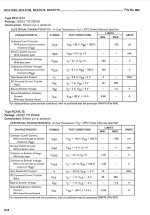
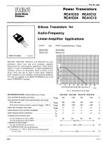
Here's a pic of the board as pulled after replacing the input differentials (Q1, Q2), the 4.7K CC resistors that connected to their collectors (both measured 5.7K or thereabouts). And the 2 "lytics which were off value. I've also included (I believe the vbe resistors Mooly mentioned (assuming he wants the ones on the bias transistor Q6. I've also included the oem datasheet and that which I replaced them with after discovering that one channel Q tested as 2 diodes.

Attachments
Here are the other transistor substitutions I made. Since the bias transistor had a special heatsink made for the TO-39 case, I couldn't use the TTC004s for it as well, though I could have drilled a new hole in the heatsink and run wires from it to the board. I doubt that's what's causing the issue since the R channel biases fine using the 2N3019.
RCA 40361 - TTC004B (I had read mention of BD139/140 for these pairs, but the fT was much higher, so stayed with the 004s)
RCA 40362 - TTA004B
RCA 1A09 - 2N3440 (TO-39 from Central Semi so will fit the finned heat sink)
2N5415 - 2N5415 (Central Semi still makes these in TO-39)
RCA 1C12 - MJE15032 (overkill, but was ordering to also have some stock)
RCA 1C13 - MJE15031 (same)
If anyone has better alternatives for the drivers, they do have a higher fT than the originals, but again, wouldn't I be experiencing the same issue on both channels if it was a question of an incorrect part substitution? There's some other options with the lower fT, but then I lose the current capability, or voltage rating....
Attachments
Have you done the measurement I suggested yesterday as that will tell us a lot about what is really happening?
What voltage range can you achieve between these two points. You are measuring across the transistor. We need the highest and lowest voltages achievable.

What voltage range can you achieve between these two points. You are measuring across the transistor. We need the highest and lowest voltages achievable.
I did not get a chance to do that yesterday, and am heading to Zurich today. I should be back Thursday night, but I don't play with electronics while jet lagged, just to be safe I don't smoke something by a probe slip.😉
Does it matter which probe (+/-) goes on the emitter vs collector?
Does it matter which probe (+/-) goes on the emitter vs collector?
Will report back Friday with what I find. Would it be helpful to do the same with the "apparently" working R channel for comparison?
Full rotation of the trimmer?
DBT or line power?
Full rotation of the trimmer?
DBT or line power?
I would not alter the good channel not least because it will over bias if you turn it all the way. You can certainly measure the good channel and you should see around 2.4 to 2.6 volts I imagine. YOu need enough voltage to overcome the four base/emitter volt drops of the driver transistors and output transistor. Each is around 0.6 volts approximately. The parallel pairs of outputs make no difference, they count as a single device.
So the channel that will not bias up is either not reaching a high enough voltage across the bias generator transistor (this 2.4 volts to 2.6 volts) to begin to turn all the output stage transistors on or else something else is amiss in the output stage but given it plays OK that is unlikely.
The 2.4 volts isn't an absolute, it depends a little on each transistor and that is why replacing all the transistors can put the bias out of range. Older transistors used different manufacturing processes and the forward turn on voltage was often just a bit lower such as 0.55 volts and that makes a big difference.
DBT or line power?
Provided it is OK with a DBT first you can go to full line voltage as that is really the result that matters.
Be aware that full line voltage can get you a slightly higher bias voltage as all the rails are that bit higher, sometimes quite a bit higher actually.
Always begin with the preset at the end that gives minimum voltage across the bias generator transistor.
One last question...
Should I pull the outputs for this voltage measurement? I realize the DBT will protect from an over-current situation, but wondered if they needed to be in the circuit for it to be a valid test.
Should I pull the outputs for this voltage measurement? I realize the DBT will protect from an over-current situation, but wondered if they needed to be in the circuit for it to be a valid test.
Last edited:
OK, here's what I found....
I first just took resistance measurements across the test points (red probe on the collector, black on the emitter of Q6) with the two channels unplugged from the power.
L fully CCW (closed): 4.27 Kohms
L fully CW (open): 3.532 Kohms
R fully CCW: 3.83 Kohms
R fully CW: 3.389 Kohms
I then plugged in one amp module at a time and took VDC readings in the same locations (all run through a DBT with a 150W bulb
L CCW: 1.452VDC
L CW: 1.794VDC (bulb was glowing dimly at this point)
R CCW: 1.593VDC
R CW: 1.852VDC (bulb glowing a little brighter than the above test of the L channel)
The L volts didn't seem to do much for the first portion of trimmer travel, but then began to increase at roughly half a turn, perhaps a little past half. The R volts responded immediately to the opening of the trimmer.
Does this point to a poorly tracking bias pot on the L channel and need replacement? The voltages I measured are nowhere near the 2.4-2.6V you mentioned. But I hesitated to place on full line power for this initial test.
EDIT: Since the R amp was still plugged in, I checked the volts with the trimmer fully closed on full line power...1.595VDC. So, with the 150W bulb in the circuit, the amp is basically getting full line power anyway.
Last edited:
That all looks pretty promising actually. The range of adjustment is pretty similar between both channels. Measuring resistances in circuit doesn't work because of interaction with other parts 🙂
So reading back to post #1 the right channel works OK and is original. You need to set this good channel to give minimum bias for now which is minimum voltage across Q6. The 1.85 volts you reach if divided by four (the four base/emitter volt drops we need to overcome) we get 0.46 volts available per junction. Old transistors (as in manufactured using older doping processes) tend to have a little lower forward voltage than modern parts which are closer to 0.6 volt.
What you need to do is reduce the value of R25 that is in series with the preset just a little. That will turn of the transistor a little more and allow more voltage to develop. I would suggest adding a resistor in parallel rather than removing it and trying to fit something else.
You will have to look what is fitted first and then add something to reduce its value just a little (say by 10% to begin with) and see if that gives enough range. Without knowing what value R25 is makes it impossible to suggest a value to add but if for example it was 1k then add a 10k across it which would make a 909 ohm equivalent and see if that gives enough range.
Always start with the preset on minimum bias setting and keep using the bulb for now.
A little correction to your above assumptions....
Yes, regarding the resistance measurements...I just thought it could provide a little idea of how the trimmer was behaving "at no cost".
The R channel is NOT original. When I had the first minimal work finished (e-caps, input differentials, and DC Offset dialed in I gave a listen. (both 4.7K resistors on the collectors of the input pair of each channel were reading 5.7+K, so one on each channel got replaced by 4.75K Dale CMF60 series, the other temporarily by a 10K trimmer which I used to zero-out the offset. The trimmer then got replaced by a close-value DALE RN60 fixed).
I would have checked and adjusted the bias at that time also, but I had no value to go by, and the only method for setting bias "provided" by the amp is 1/4" out jacks to a scope, which I don't have. So, I gave a listen and then worked out where I needed to tack some meter hooks on the emitter resistors in order to set bias using the method I'm familiar with. That is when I discovered that the L channel bias didn't really increase and R channel, even at minimum, was 12mV. that prompted me to get the boards off the heatsinks and start testing the transistors, measure resistor values, etc. When I discovered that many of the Qs only tested as diodes, I looked for modern replacements. So, the L channel got all new transistors, where the R got cobbled together the best Qs from both channels. Both channels got new drivers (MJE15032/15033) as the NPN from each pair didn't test good, just as double-diodes.
At that point It went back onto the bench to see what happened regarding bias. R channel came up right away, L was slow to respond to trimmer movement (just like the voltage measurements showed from today). I was eventually able to set both channels to 14mV (~32mA bias current), though the trimmer was about fully open on the L channel and only partially opened on the R. Both were stable and DC Offset was roughly 2mV each channel IIRC, so another listening test was started.
Test disc was Thomas Dolby's Flat Earth and the track was Dissidents (which has some good bass notes). I was bringing the volume up to a "decent" listening level, when a sharp noise was heard and the R channel shut down as the fuse (6A) blew. I replaced it with a 2A, DBT...glowing bulb....not good. Disconnected the R amp module and no issue on the DBT with only the L channel hooked up. R amp alone causing issues, and that was the one with the OEM transistors. One of the outputs and one of the new drivers were toast. So, I now didn't trust the aged Qs of the R channel, and since the L channel didn't reveal any issues, except the initially non-responsive trimmer, I replaced the R channel Qs with my subs.
So, today's voltage measurements were taken on boards that have all new replacement transistors. I am suspecting poor tracking of the trimmer, even though I pulled and measured it early in the component test "phase" of this project. Once I do that I will report back.
Here is the link to the AK thread, which you should be able to read through if desired to see where and when any changes took place better than my above summary.
https://audiokarma.org/forums/index.php?threads/epicure-m1-amplifier-restoration.1063143/
Pulled the nominal 1K trimmer....
0.806 Kohms across the terminals
wiper closed - 0.806K
~1/4 turn - 0.773K
~1/2 turn - 0.456K
~3/4 turn - 274 ohms
full turn - 34 ohms
I have not pulled the R amp trimmer, but i would suspect that by 1/4 turn it's < 0.77K. So, I'm going to see what I can hook up as any time I need to access the component side of the board, I have to pull everything and unscrew it from the heat sink.
- Home
- Amplifiers
- Solid State
- Epicure M1 Giving me Biasing fits