
Where can I purchase those tweezers?
That photo is from Amazon, if you search for helping hands tweezer holder I think it comes up, along with others.
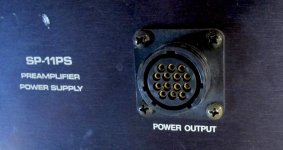
For reference, here is what Audio Research used for the SP11:
These pins are pretty close together, that's reassuring compared to the connector I chose which has more gap. 14 pins here vs the 10 I did. Someday it would be interesting to design higher pin count cables.
I have used those connectors from Ali for connectors to a three way actively crossed-over speaker. They worked great.
@Windcrest77
In your first post you mention a rating of 1000V for these connectors. On the Aliexpress page I can only find 400 to 500 volt specs. The specs are actually a bit contradictive. On the specifications tab hey are listed as "voltage 415V" and "rated voltage 400V/500V". Not sure how to interpret. 500V would be find for me but 400 or 415 would be on the low side for my projects.
Thanks
John
Audio Res used AMP connectors for that model. You may also want to take a look at the Bulgin connectors which are available from Mouser.These pins are pretty close together, that's reassuring compared to the connector I chose which has more gap. 14 pins here vs the 10 I did. Someday it would be interesting to design higher pin count cables.
I think that both Hallicrafters and Heath used the Cinch-Jones connectors for connection between their transceivers and power supplies.
Why would you even consider 5000v outside the grounded chassis. This is an accident waiting to happen.
Do go there 1 mistake is deadly.
Do go there 1 mistake is deadly.
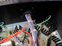
Not to go off topic but I've had great luck for years with Speakon connectors for umbilicals, even with high voltages. The pins are nicely spaced and even have plastic dividers between them for added assurance against short circuits. They also twist-lock on very easily and securely compared to press-on pins.
I know they are not rated for this usage but I believe that's mostly to prevent roadies from plugging high voltages into stage speakers, as Speakons are meant to be speaker connectors. I know better in my home setup...;-)
Here's one example in a preamp I built:
I know they are not rated for this usage but I believe that's mostly to prevent roadies from plugging high voltages into stage speakers, as Speakons are meant to be speaker connectors. I know better in my home setup...;-)
Here's one example in a preamp I built:
Attachments
@Windcrest77
In your first post you mention a rating of 1000V for these connectors. On the Aliexpress page I can only find 400 to 500 volt specs. The specs are actually a bit contradictive. On the specifications tab hey are listed as "voltage 415V" and "rated voltage 400V/500V". Not sure how to interpret. 500V would be find for me but 400 or 415 would be on the low side for my projects.
Thanks
John
Sorry about that, I made a mistake, I went through so many models. These are rated 500VAC which equates to 700VDC, enough for most projects. Encapsulating the solder cups in RTV might allow some voltage above 700 by eliminating all the air.
Another tip. I realized that some people might yank on the outer jacket to unplug instead of properly yanking by the connector. It won't do any harm as the outer jacket is floating from the wires, but they might yank it out of the clamp. So to avoid this you can wrap electrical tape around the outer jacket inside the shell. Around and around until you've built up 2mm or so of tape. Similar to how old radios tied a knot in the power cord so it can't be yanked out of the back. So this is how I'd protect against cord yanking, just open the shell, add the tape and reclose the shell.
I corrected the first post voltage rating. But remember that PTFE silver wire has an insulation rating of 600 volts. So basically using the wire I used and the connector I used, the connector rating exceeds the wire itself! You have to think of everything in the chain. If I were making an umbilical for an Amp with a 1200VDC B+, I'd go with a larger diameter all plastic connector and use some 30 KV 22AWG wire, and encapsulate all the cups in RTV, permanent. For this post I would stay 550VDC tops.
Last edited:
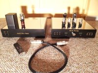
I've had good luck with these Chinese military 7-pin connectors in my phono preamp builds. They have M and F versions. 2 16ga wires for the heaters and the rest can be 18ga, 2 b+ and 2 HV returns and the middle one is chassis ground. Mesh sleeving and heat shrink tubing to bundle the wires, but don't put the hot air on the mesh, it'll melt!
Why would you even consider 5000v outside the grounded chassis. This is an accident waiting to happen.
Do go there 1 mistake is deadly.
As you will notice I wrote "thought about"....
Hello Windcrest77
Thank You very much for this much needed topic ( for us beginners in two box design ) !
How strong the soldering iron are You using for these connectors & 18AWG wire ?
Is the 60 Watt Iron enough or better to work with 100 Watt Soldering Iron ?
Thank You very much for this much needed topic ( for us beginners in two box design ) !
How strong the soldering iron are You using for these connectors & 18AWG wire ?
Is the 60 Watt Iron enough or better to work with 100 Watt Soldering Iron ?
Ah the solder, yes, you dont want to have to struggle with that, good question.
More important than the wattage is that you have the correct tip, 60 watts I would think is fine, 100 even better, (I'm not even sure what power my soldering station is). Don't use a real sharp tip like you would use for very small solid state stuff. I'm using a chisel shaped tip that is 2mm x 1mm at the very point, it can spread the heat, I'm at about 360 degrees C (680 F). Even a 2.5mm chisel tip should work as long as you can fit it between the inner solder cups. Position the tip toward the back of the solder cups seemed to work best, then apply the solder (leaded) so it fills the whole cup. Solder from the bottom row going up and the farthest pin on each row going towards you, one row at a time, you'll find pins 9, 5 and 6 to be the hardest because they are the inner pins, the outer pins are easy access, and pins 1, 2 and 3 the easiest (top row no obstructions). Also remember that the female and male connectors read their pin numbers opposite. I solder one side, then I fully document what color wire goes with which pin and draw a diagram. Then when I solder the other side I'm double checking the color and the pin numbers are correct, you can even continuity test to make sure. Don't forget to slip the shell and ring onto the tubing correctly first before soldering the second side!
I'm using my favorite solder Kester 63/37 63% tin 37% lead .031 inch (.7874 mm) diameter:
Kester 24-6337-0027 Solder Roll, Core Size 66, 63/37 Alloy, 0.031" Diameter
Last edited:
Thank You very much !
Think that You're right about tip being more important.
Mulling the question after posting it, remembering what i used for solid core wire, AWG18-20, methinks that 60W power station is enough.
Didn't work witht the chisel tip for a last few years, used conical but for this will find chisel one ( need it anyway, sometimes soldering is easier with chisel tip, Ersa had some chisel tips 2,3mm wide which were excellent for work ).
Thanks & regards, Krca
Another connector which seems pretty decent and reasonably priced is JAE. Mouser offers these. This is what was used on a Counterpoint SA5 preamp I used to own for the umbilical between the psu and the preamp (tube).
Post #32 is incorrect it turns out PTFE wire, and most wire ratings are done in AC. 600VAC equates to 840VDC for PTFE insulation. I added voltage rating for the whole assembled cable, if built as shown to post #1. Basically 700VDC for the whole cable pins 1-7.
- Home
- Amplifiers
- Tubes / Valves
- Making high voltage umbilical aircraft inter-connects