I'm looking for a model of a planar electrostatic speaker represented by physical components, similar to the speaker model presented in this Stereophile magazine article. Although an electrostatic speaker is often described as acting like a capacitor it is also usually quoted as having a nominal impedance, usually 4 ohms. Since a capacitor's reactance varies continuously with frequency it would not seem to have a "nominal impedance" so I'm thinking that the speaker model must be more complex than just a simple capacitor. Does anyone have a model that is a good representation of an electrostatic speaker?
According to Walker's equation, for frequencies above the fundamental resonance and below the frequency where diaphragm mass comes into play, a flat-panel electrostatic loudspeaker must be driven with a frequency-independent current to get a flat response in the far field.
Therefore, the step-up transformer should not be connected straight to the stators. In fact, the stators should be segmented and driven via some sort of crossover filter. In the ESL 63, a damped artificial transmission line is used for that.
All in all, it depends a lot on the electrostatic loudspeaker design. I know there is a thread about modelling the ESL 63 somewhere.
Edit: this is it: https://www.diyaudio.com/community/threads/quad-63-and-later-delay-line-inductors.338927/ That is, it diverged into a discussion about ESL 63 modelling.

I found this very informative article on the Quad ESL impedance:
http://www.audiomisc.co.uk/57and303/interact.html
I decided to verify the impedance plot on my speaker, so I used an audio signal generator, a series resistance and an audio voltmeter. I set up the level so that 40mV on the voltmeter corresponded to 10 ohms. Then I entered the measured values in an Excel table and I got this impedance diagram:

I wondered how accurate is the electrical model against the measured values, so I created an LTSpice model. See .asc file attached. I had to modify the...
http://www.audiomisc.co.uk/57and303/interact.html
I decided to verify the impedance plot on my speaker, so I used an audio signal generator, a series resistance and an audio voltmeter. I set up the level so that 40mV on the voltmeter corresponded to 10 ohms. Then I entered the measured values in an Excel table and I got this impedance diagram:
I wondered how accurate is the electrical model against the measured values, so I created an LTSpice model. See .asc file attached. I had to modify the...
- lcsaszar
- Replies: 5
- Forum: Planars & Exotics
Stereophile measured the Sound-Lab A-1. https://www.stereophile.com/content/sound-lab-1-electrostatic-loudspeaker-measurements
The impedance at high frequencies was very close to a capacitor.
Ed
The impedance at high frequencies was very close to a capacitor.
Ed
The Quad ESL model looks to be realistic and is comparable in form to the Kantor/Atkinson model presented in the Stereophile magazine article I cited earlier. I added node labels to the LTspice .asc file and then created a subcircuit from that (both attached). I then tried this speaker model in place of a load resistor in several of my power amplifier simulations, and it does give reasonable looking results.
Thanks to all. I think I have something that I can work with.
Thanks to all. I think I have something that I can work with.
Attachments
Member Hans Polak has developed a detailed model for the QUAD ESL 63, including the step-up transformer and the physical parts of the transmission lines. I have done measurements on the speaker and can confirm that Hans' model is very accurate.
Note that the QUAD is much different from other ESLs; for instance, the Martin Logans are much more like a capacitor.
So there's not one model that fits them all.
Jan
Note that the QUAD is much different from other ESLs; for instance, the Martin Logans are much more like a capacitor.
So there's not one model that fits them all.
Jan
Martin Logans are curved as far as I know, so most of what I wrote in post #2 does not apply to them.
Thanks, Jan. I'll check it out.Member Hans Polak has developed a detailed model for the QUAD ESL 63
Here's Hans' detailed model, which includes the xformer, diaphragm resonance, proxinmity effect at 1m, baffle effect and stator transparency. Did I say detailed?
But you can simplify it a lot - my measurements with the Bode100 analyzer show predominantly resistive around 400k between 500Hz and 12k.
Jan
But you can simplify it a lot - my measurements with the Bode100 analyzer show predominantly resistive around 400k between 500Hz and 12k.
Jan
Attachments
Thanks, Jan. This model does indeed qualify as "detailed." I'll spend some time studying this one.
I have no clue about SPICE. Can someone show a circuit diagram?
Also, it might be nice to apply these models to electrostatic headphones. I measured my Stax 9k here:
Also, it might be nice to apply these models to electrostatic headphones. I measured my Stax 9k here:
How well does this super simple model work out? I made a few measurements using my Stax X9000 headphone. This figure shows...If the estat is modelled as simple capacitor with a typical capacitance of C = 100 pF (that's surely not be the most accurate model of an estat!), the current ... Driving the capacitance with a sine signal at 500 Vpk, the peak current would be 6.2 mA at 20 kHz, 16 mA at 50 kHz, or 31 mA at 100 kHz. We may not need to drive the estats to full output at 100 kHz, and the power spectrum of music signals is typically quite a bit lower at treble frequencies.
For clarity, what I wrote in post #2 does not apply to headphones. Electrostatic headphones are meant for listening in the near field, so they have to be driven by a frequency-independent voltage rather than current (when certain assumptions are met).
The "Trafo" symbol used in Hans' .asc file is missing. Do you have that, or can you point to a post that has it?Here's Hans' detailed model.
Would you be willing to share your simplified model here?But you can simplify it a lot - my measurements with the Bode100 analyzer show predominantly resistive around 400k between 500Hz and 12k.
Rename the .txt from the asy.
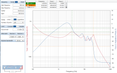
I don't have a sim[plified model, I measured the real thing.
This is the measurement of the speaker at the transformer secondary (without the xformer), HV bias applied.
Jan
I don't have a sim[plified model, I measured the real thing.
This is the measurement of the speaker at the transformer secondary (without the xformer), HV bias applied.
Jan
Attachments
- Home
- Design & Build
- Software Tools
- Electrostatic Speaker Model