Hello,
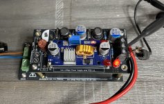
I developed two general purpose PCBs to be used with popular DC-DC setup up or step down Chinese modules like the XL4015 or the XL6009.
I developed these PCBs to generate 6.3Vdc for heating the KT88 tube filaments for one of my Tube Amplifier but it is especially interesting because it supports many DC-DC module models allowing it to be used to generate various voltages.
The LVPS-PCB-MINI (90x44) works with a simple diode bridge or with an AC-DC power supply.
The LVPS-PCB-MINI supports four DC-DC module size.
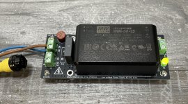
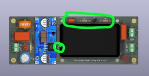
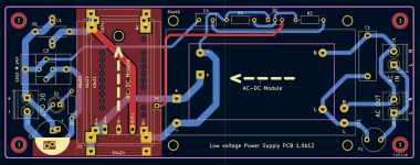
The second PCB (110x44mm) will works directly from the mains voltage via the use of various AC-DC modules from Meanwell, Recom or Hi-Link up to 40W.
The LVPS-PCB support these AC-DC modules:
Gerber files are available on my Github repository.
Regards,
Stef.
DC-DC modules that I'm currently testing.
XL4015 step down: https://fr.aliexpress.com/item/1005007168974223.html
HW-468 (TPS40057) 5V step down: https://fr.aliexpress.com/item/1005006117154837.html
[NOT GOOD] HW-469 (FP5139) step down/up: https://fr.aliexpress.com/item/1005006351906660.html
CR-6030L step down: https://www.aliexpress.com/item/1005006083560198.html
[NOT TESTED] ND04BOTA step up: https://www.aliexpress.com/item/1005007431004593.html
XL6009 step up and step down/up (4 models):
Ali's links are given as an example.
EDIT:
21/02/2025: Updated LVPS-PCB-MINI to 1.1 version. Gerber files are available on my Github repository.
24/03/2025: Updated LVPS-PCB to 1.10.2 version. Gerber files are available on my Github repository..
.
.
I developed two general purpose PCBs to be used with popular DC-DC setup up or step down Chinese modules like the XL4015 or the XL6009.
I developed these PCBs to generate 6.3Vdc for heating the KT88 tube filaments for one of my Tube Amplifier but it is especially interesting because it supports many DC-DC module models allowing it to be used to generate various voltages.
The LVPS-PCB-MINI (90x44) works with a simple diode bridge or with an AC-DC power supply.
The LVPS-PCB-MINI supports four DC-DC module size.
The second PCB (110x44mm) will works directly from the mains voltage via the use of various AC-DC modules from Meanwell, Recom or Hi-Link up to 40W.
The LVPS-PCB support these AC-DC modules:
- Meanwell IRM-15
- Meanwell IRM-30
- Hi-Link HLK-15M
- Hi-Link HLK-20M
- Hi-Link HLK-40M
- Recom RACM30
Gerber files are available on my Github repository.
Regards,
Stef.
DC-DC modules that I'm currently testing.
XL4015 step down: https://fr.aliexpress.com/item/1005007168974223.html
HW-468 (TPS40057) 5V step down: https://fr.aliexpress.com/item/1005006117154837.html
[NOT GOOD] HW-469 (FP5139) step down/up: https://fr.aliexpress.com/item/1005006351906660.html
CR-6030L step down: https://www.aliexpress.com/item/1005006083560198.html
[NOT TESTED] ND04BOTA step up: https://www.aliexpress.com/item/1005007431004593.html
XL6009 step up and step down/up (4 models):
- XL6009 basic blue model (caps 100/220uF)
- [BEST] XL6009 Red module (caps 220/220uF + more HF filtering)
- [NOT GOOD] XL6009 Red step down/up module (caps 220/220uF, more HF filtering, 2 big inductors)
- [NOT GOOD] XL6019 basic blue model (caps 100/220uF)
Ali's links are given as an example.
EDIT:
21/02/2025: Updated LVPS-PCB-MINI to 1.1 version. Gerber files are available on my Github repository.
24/03/2025: Updated LVPS-PCB to 1.10.2 version. Gerber files are available on my Github repository..
.
.
Attachments
Last edited:
Hi they exist already in low loss linear uLDO version.
I made a batch of MIC5156 based LDO supplies, parts cost is 15 euro selling these for €27.50 for my troubles in assembly and testing, ex shipping. Will ship worldwide at cost.
I have 6 available that arent spoken for, Reichelt will deliver the coolers sometime this week, and then its an afternoon of soldering to get them ready to ship.
Photo attached of my previous batch.
Fully tested and assembled, €27.50 or about 30USD.
Boards are good for 2.5A provided the winding can deliver that much current as the 2x 15mF 10VDC has quite an ugly current waveform.
Once these run out, i will do...
- v4lve lover
- Replies: 132
- Forum: Swap Meet

HI,
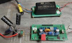
This is another way of doing it.
I tested the version with bridge in "flying" wiring until 2.4A at 6.3V and it seems to work well but I have not yet done the measurements and torture tests. The advantage of the AC-DC and DC -DC modules is that it does not heat up at all and that you can use both step up and step down modules.
I don't plan on making ready-made kits, but just making the files available for anyone who wants to test and use them.
Stef.
Supported modules (and others variants):
https://fr.aliexpress.com/item/1005007168974223.html
https://fr.aliexpress.com/item/1005006351906660.html
https://fr.aliexpress.com/item/1005006760900178.html
Last edited:
If they have clean power and no EMI all is good. Slow ramp up to protect the filaments against cold state inrush current would be nice. In fact that would seem mandatory considering scarcity and prices of NOS tubes.
Last edited:
Hi Stef, it may be a bit confusing to some to start describing your pcb, but then later refer to it as a 'module' after you have firstly referred to the cheap pre-made unit as a 'module'.
Yes, wrong sentence "I mainly developed these modules to generate 6.3Vdc for heating the tube filaments.". Fixed.
Read "PCBs" instead of "modules".
I also tested the bridge version with an step up XL6009 using a transformer with 5Vac windings to output 5Vdc at 1.3A. Very useful.
If I'm not mistaken, the AC-DC IRMs from Meanwell have a built-in softstart and maybe some modern DC-DC modules have too. I also provided 4 M3 holes on the large PCB to be able to put a board to adapt other AC-DC modules.
When I have PCBs I could measure.
Last edited:
On the XL6009 modules I looked at 2 yrs ago, with pcb marking XTW-SY-8, they used a SS34 diode (40V schottky); 33uH inductor; 220uF 35V input; 100uF 50V output. The trimpot could adjust output to >40Vdc so be careful. Output port noise can exceed 1mVrms wideband (to 600kHz) when there is little loading. The pcb does a pretty good job with the layout, but note that the metal tab of the XL6009 and its underneath pcb land are at the switching voltage, so electrostatic shielding and separation distance from other parts on the main pcb may be of some benefit, especially if the configured output voltage is high. The XL6009 incorporates current mode control, so depending on the cold heater load current (if that is the application) at turn-on, the module may inherently limit heater current for a second or two until the heaters warm up. However that depends on what is powering the XL6009, as that source may have a limit or hiccup response, and may interact with the XL6009 UVLO (although the datasheet is pretty silent on that capability, but it may be circa 5V).
Hi,
The softstart function of the XL6009 seems to work well. I don't have a large current draw at startup.
I would however be interested in more precision on this sentence "so electrostatic shielding and separation distance from other parts on the main pcb may be of some benefit".
On the other hand with the XL4015 it is not the same thing. I have a big current peak at startup. I am currently testing it. I will post the results later.
I also have to test this module that I am waiting for this week.
https://www.aliexpress.com/item/1005006351906660.html
Stef.
The switch node in the XL6009 is a squarewave with a voltage changing abruptly between about 0V, and a level equal to a bit more than the output dc voltage. If your application needed say 24Vdc output then that squarewave may be large enough to couple in to nearby parts/circuitry through capacitive coupling. That noise leakage can be suppressed by distance to nearest parts, or using an electrostatic shield.
I don't have an XL6009 to try with the scope at the moment.
I did some tests with the XL4015. It seems to behave well except that it doesn't have softstart.
I made the ripple measurements of the basic circuit in "flying" wiring. We go from 82mV to 3mV depending on the configuration.
Module tested: XL4015
Input voltage: 15Vdc
Output voltage: 6.3Vdc
Target amperage: 1.5A (with 4R 100W load)
Consumption at 15v: 840mA (12W)
Consumption at 5V: 1.5A
Module alone.

Module with a 330uF at input

Module with a 330uF at input and a 1500uF at output

Module with a 330uF at input and a CRC composed of 220uF (on the module) + 10mH 0R1 inductor + 1500uF at output

The inrush current at start up drawing 1.5A with 1500uF output caps seems to be around 1.3A on the 15V input (less than one second). I don't have the climb curve.
Max output caps seems to be 2200uF. More capacitance degrades the specs and the inrush current draw increases again.
I left it on for 2 hours and I still have 6.3V output when I come back. It only moves on the third digit.
Stef.

I did some tests with the XL4015. It seems to behave well except that it doesn't have softstart.
I made the ripple measurements of the basic circuit in "flying" wiring. We go from 82mV to 3mV depending on the configuration.
Module tested: XL4015
Input voltage: 15Vdc
Output voltage: 6.3Vdc
Target amperage: 1.5A (with 4R 100W load)
Consumption at 15v: 840mA (12W)
Consumption at 5V: 1.5A
Module alone.
Module with a 330uF at input
Module with a 330uF at input and a 1500uF at output
Module with a 330uF at input and a CRC composed of 220uF (on the module) + 10mH 0R1 inductor + 1500uF at output
The inrush current at start up drawing 1.5A with 1500uF output caps seems to be around 1.3A on the 15V input (less than one second). I don't have the climb curve.
Max output caps seems to be 2200uF. More capacitance degrades the specs and the inrush current draw increases again.
I left it on for 2 hours and I still have 6.3V output when I come back. It only moves on the third digit.
Stef.
Last edited:
Hello,
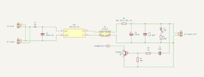
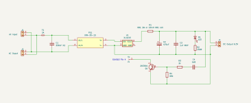
In your opinion, will this circuit work as softstart for modules that do not have a built-in softstart?
The circuit connects to the Out+ and Out- and to the Vc pin (n°4) of the XL4015 chip.
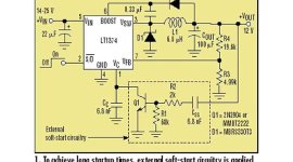
I based myself on this yellow circuit.
This circuit will fit on the PCBs.
Stef.
In your opinion, will this circuit work as softstart for modules that do not have a built-in softstart?
The circuit connects to the Out+ and Out- and to the Vc pin (n°4) of the XL4015 chip.
I based myself on this yellow circuit.
This circuit will fit on the PCBs.
Stef.
Attachments
This should be implemented/tested as it is an essential feature for a filament DC power supply. If it can not be implemented then the XL4015 modules are too cheap/not suitable for the intended purpose.
I think many would prefer to spend more so their tubes will live longer. Most transformers also have 6.3V windings so with high chance of not having a power on maximum current surge. Things were simple and pretty adequate. A DC PSU (with about always the same power on behavior to its load) must have protection against that to be able to compete with the original way of doing stuff.
I think many would prefer to spend more so their tubes will live longer. Most transformers also have 6.3V windings so with high chance of not having a power on maximum current surge. Things were simple and pretty adequate. A DC PSU (with about always the same power on behavior to its load) must have protection against that to be able to compete with the original way of doing stuff.
Last edited:
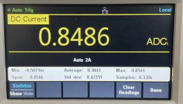
Well, I'm not sure that there is an inrush current at startup with the XL4015.
I connected my table multimeter in current mode and fast acquisition and I don't see the inrush peak.
I'm still with the same config. 15V input and 6.3V 1.5A output.
I must have a strange behavior with my laboratory power supply. If I set the CC protection to 1A, the XL4015 module does not start and the CC protection starts on the lab power supply. If I set the power supply protection to 1.3A, the XL4015 module starts as it should.
Weird.
Stef.
Attachments
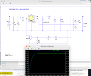
This is exactly what is meant. The loads behavior at power on requires slow ramp up of output voltage to filaments.I found a library for the XL4016 (almost the same as the XL4015) for LTSpice and the softstart seems to work.
What you describe is probably the inrush current of that PSU that requires more current at cold start. A relatively normal phenomenon with switchers as they are often a capacitive load.
Last edited:
Hi,
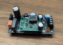
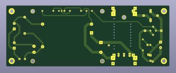
I added two more footprints for the HW-468 (step down) and HW469 (step up/down) modules in addition to the XL4015 and XL6009.
I haven't looked at the type of chip on these 2 new modules yet.
I also added a ground plane below the DC-DC modules.
Stef.
I added two more footprints for the HW-468 (step down) and HW469 (step up/down) modules in addition to the XL4015 and XL6009.
I haven't looked at the type of chip on these 2 new modules yet.
I also added a ground plane below the DC-DC modules.
Stef.
Attachments

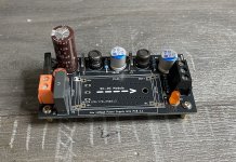
Here is the latest updated version.
I will try later to test the softstart circuit for the XL4015 live to see if this still triggers the labs psu CC.
Stef.
I will try later to test the softstart circuit for the XL4015 live to see if this still triggers the labs psu CC.
Stef.
Attachments


Hello,
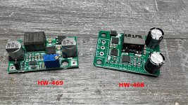
For those who would be interested in the HW-468 5V module, it is very easy to switch it to adjustable voltage.
You just have to either put a 10K trimmer on the two red points or directly put a 402 resistor of the correct value. It is also possible to replace the Schottky diode D2 by a 4A CMS fuse. This improves performance.
The HW-469 module is not great. It does not work very well in step up. From a voltage of 5V at the input, you cannot make 5V or more. It goes into protection or does not output anything. Disqualified. So far I have not found a module that can compete with the excellent XL6009 or XL6019.
Regards,
Stef.
Attachments

The XL6009 incorporates current mode control, so depending on the cold heater load current (if that is the application) at turn-on, the module may inherently limit heater current for a second or two until the heaters warm up. However that depends on what is powering the XL6009, as that source may have a limit or hiccup response, and may interact with the XL6009 UVLO (although the datasheet is pretty silent on that capability, but it may be circa 5V).
HI!
I made more testing with the last batch of XL4015 module I received.
I've done tests at 6.3V 1.6A. The IRM-30-15 is a bit short. 1.3-1.4A seems more reasonable to avoid it getting too hot. From the cut, I switched to a 12Vac 4.5A toroid + bridge power supply.
When you start the module, it limits the current in two steps. You can see on the display, one step towards 4.5V and another at 6.3V. By default the ramp is 8ms (Ccf = 120nF) but it can be easily modified.
The module does not support more than 2200uF in the output capacitor (in addition to the one on the module). If you put more you lose efficiency, the ripple moves up and this draws more current from the power supply.
It needs at least 10V at the input for it to work properly.
The ripple is about 2-5mV depending on the capacitors behind and the CLC. The running frequency is 100KHz. 80mV bare without capacitors or CLC.
It does not heat up or almost even at 1.6A.
I also tested the HW-468 module. The ripple is better, between 1.5mV and 2mV. It has a softstart and many protection inside.
Stef.
Ps: I upload the last LTSpice files on Github.
Picture of the tests with 22uF in Ccf. This gives a ramp of 1200ms. I ordered myself some 22uF 805s to try out.
I also reworked the AC version PCB. I gained 10mm, 90x44mm now.
Attachments


Last edited:
- Home
- Amplifiers
- Power Supplies
- Power Supply PCB for DC-DC modules as XL4015, XL6009 and others