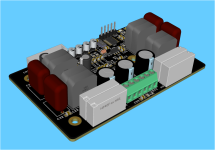
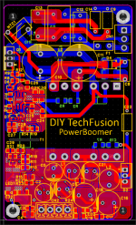
Hello , I want to share my on-going project, DIY Class D amplifier Module for Active speaker and Battery Powered Boom Box.
If you are interested with this project , please comment any suggestions.
If you are interested with this project , please comment any suggestions.
Attachments
Firstly, great work! While this isn’t exactly my area of interest, I acknowledge that these chip amplifiers already come with some built-in protections.
Suggestions for Improvement:
Suggestions for Improvement:
- Expand Protection with I2C Interface:
- Implement an I2C interface with programmable resistors to enhance flexibility and functionality.
- Utilize Internal EEPROM for Threshold Storage:
- Leverage the internal EEPROM to store thresholds.
- ST’s chip program is reliable for up to 10 years.
- Consider using a PIC microcontroller for its stability and suitability in applications where code like this rarely changes.
- Enhance Analog Front-End Stages:
- Improve the analog front end at each stage by incorporating BJTs buffers for better performance.
- Simplify Oscillator Design:
- Eliminate the crystal oscillator (XTAL) and use the internal RC oscillator instead.
- This reduces routing complexity and avoids interference in this section, as precise timing is not critical in this application.
Hello,
Thanks for the feedback.
I will add the external interface BLE & GPIO in the next version.
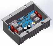
Yes Preamplifier, Volume, Tone control and Bar EQ display will be included in the Final assembly , I am still working on the 3D printed cover design to house the other subsystems.
I prefer working with ST ( Arduino code compatibility) than Microchip, I will be adding BLE so I included the XTAL.
Thanks for the feedback.
I will add the external interface BLE & GPIO in the next version.
Yes Preamplifier, Volume, Tone control and Bar EQ display will be included in the Final assembly , I am still working on the 3D printed cover design to house the other subsystems.
I prefer working with ST ( Arduino code compatibility) than Microchip, I will be adding BLE so I included the XTAL.

You cannot get sub 100us response times using an Arduino, but then again you NOT doing fast overcurrent trips this is a novel protection scheme.Hello,
Thanks for the feedback.
I will add the external interface BLE & GPIO in the next version.
Yes Preamplifier, Volume, Tone control and Bar EQ display will be included in the Final assembly , I am still working on the 3D printed cover design to house the other subsystems.
I prefer working with ST ( Arduino code compatibility) than Microchip, I will be adding BLE so I included the XTAL.
Fast protection (100uS) is done by the Class D amplifier hardware through cycle by cycle PWM current limiting, the MCU is only be use for housekeeping, slow Speaker protection, and special features,
such as Bluetooth control shutdown, Bluetooth Volume control vis Digital Potentiometer, Operating Status indication
such as Bluetooth control shutdown, Bluetooth Volume control vis Digital Potentiometer, Operating Status indication
Last edited:
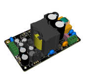
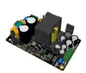
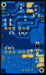
Low Noise Power Supply design for the TAS5630B with two outputs 48V and Regulated 12V, good primary EMI filter and secondary LC filter to reduce output ripple.
Attachments
I see that you're using the QFN package with the close-to-clipping indicator.
As the power supply you're using is a PWM based design it should have the possibility to operate at a wide variety of output voltages.
It would be really neat if you could add in the capability for the microcontroller to adjust the supply voltage based on the audio requirements.
I'd probably add in two voltage levels. Say 25V (chip minimum) for idling, and quiet listening, then a jump up to 50V when the clipping indicator trips. Add in a delay of five minutes, or so, before the system tries to lower the voltage back down again. You could also add in a feature to lower the PSU voltage right down (below 25V) should a system error be detected as a way of minimising potential damage.
Connect the clip indicator to an interrupt input, on the micro, for a quick response with an ISR, and then use a solid state switch to alter the feedback resistor value to jump between high and low voltages (you could use the switch to short out one of a pair of series connected resistors that form the bottom of the feedback network). The nice thing is that this should be possible in a way that means the system still works fine even if the variable voltage system doesn't work or fails and a solid state switch would only need a GPIO to operate.
The most obvious benefit of this is reduced power consumption at idle and low listening levels. This should improve reliability by keeping everything cooler. The other benefit is that the output noise of these amplifiers tends to go down a little with lower supply rails. You'll also get lower EMI.
Thank you for the feedback, I will also add that clipping feedback function to the Power Supply Feedback, my initial control is by adjusting the signal from the preamplifier via digital potentiometer volume control to reduce the clipping. User can also reduce the volume through BLE remote.

- Home
- Amplifiers
- Class D
- High Performance & Fully Protected 300W Stereo Class D Amplifier using TAS5630B