Psst
To be on the safe side, I limited the thickest ship I had to build professionally to 70V times 7A (rails +/-90Vdc), the requirements were 100Vpk and 10Apk ... Nobody noticed. Completely symmetrical; but the 4 or 5 parallel output stages consisted of IRFP ... common source!!!
At the same time, the actual current flow and voltage should be displayed ... Development time with various test setups approx. three months. Basically, everything was quite simple - afterwards.
That was my summer in 2005 (back to university) , when I still had things to prove.
980Wpeak at 1Ohm;
two large fans were required, some NTCs and others. An interesting automatic switch-on ..!

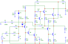
That s just symbolic schematics, not iterations of your schematics.
H2 being the main harmonic is not forcibly a good thing, often this is an indication that the amp is unbalanced
and that it produce a high level of H2 as a consequence, this is obvious when FI H2 is say 20dB higher than H3,
hence what is perceived as good is actualy the result of a flaw, in your case this amp beg an EF buffer between
Q5 and Q3, that will get the signal path using 7 transistors and reduce THD + IMD greatly.
Also, as demonstrated by D. Self, a quasi complementary OS is to be discarded as it produce quite more THD
at low power than a compmentary OS, when power decrease the harmonics level keep being constant in absolute value.,
that s why QC were progressively abandonned once affordable PNP parts became available.
Got it 😎That s just symbolic schematics, not iterations of your schematics.
You can see that immediately from the schematic, and it's simply part of the old-school theme.H2 being the main harmonic is not forcibly a good thing, often this is an indication that the amp is unbalanced
I'll try that out right away, that's what this thread is for! But remember, I'm a child of TIM indoctrination -> I simply can't change that anymore. Well, let's lower the load on the one transistor IPS and increase the OLG of the entire system.and that it produce a high level of H2 as a consequence, this is obvious when FI H2 is say 20dB higher than H3,
hence what is perceived as good is actualy the result of a flaw, in your case this amp beg an EF buffer between
Q5 and Q3, that will get the signal path using 7 transistors and reduce THD + IMD greatly.
And for years I have been stumbling over these statements by Mr. D. Self, as he himself uses this OPS in his Class A Blameless example. Since Mr. D. Self also repeatedly fabricates a few knockers, my split personality, the 'Haudegen' in me, has lovingly given him the working name Salguod Fles - internally we only talk about Salguod Fles.Also, as demonstrated by D. Self, a quasi complementary OS is to be discarded as it produce quite more THD
at low power than a compmentary OS, when power decrease the harmonics level keep being constant in absolute value.,
that s why QC were progressively abandonned once affordable PNP parts became available.
I sincerely hope he doesn't hold it against me 😊.
HBt.
PS lets take a look!
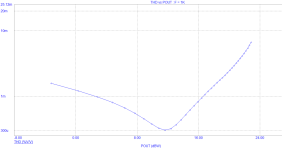
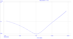
+10dB OLG, which can still be described as moderate. We are slowly approaching the “utopian THD”.
A standard, completely unmotivated Darlington makes it possible. Is more possible? Will the customer (or client) like the sound? Strangely enough, I can already hear the CEO Alois Reutler - and in my mind's eye I see Haudegen and Alois in constant conflict, a love-hate relationship, toxic.
A standard, completely unmotivated Darlington makes it possible. Is more possible? Will the customer (or client) like the sound? Strangely enough, I can already hear the CEO Alois Reutler - and in my mind's eye I see Haudegen and Alois in constant conflict, a love-hate relationship, toxic.
Let's just move away a little from the pink cloud and ensure better symmetry of the quiescent currents of the Q6 & Q7 pair, which are now exactly the same size!
This THD value is also acceptable /for the old school theme.

This THD value is also acceptable /for the old school theme.
This topology is a real playground and if it were possible to manifest the THD as a function of power without the bathtub, as a horizontal line, then we would have already found the holy grail.

tpc
tpc
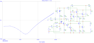
We can also simply make the bathtub look like this. This is possible by slightly increasing the negative feedback factor, RF = 75Ohm (without changing the bandwidth of the system).
The customer must decide which sounding he prefers. We can set almost anything that is desired ..!

The customer must decide which sounding he prefers. We can set almost anything that is desired ..!

+10dB OLG, which can still be described as moderate. We are slowly approaching the “utopian THD”.
A standard, completely unmotivated Darlington makes it possible. Is more possible? Will the customer (or client) like the sound? Strangely enough, I can already hear the CEO Alois Reutler - and in my mind's eye I see Haudegen and Alois in constant conflict, a love-hate relationship, toxic.
Connect the IPS and VAS transistors this way and see the result...
Attachments
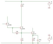
As Darlington with Cq8 = Cq3Connect the IPS and VAS transistors this way and see the result...
As you suggest with 4.7kOhm up to Vcc=30Vdc
Now with the BC-141-C as Q3 (not BD139-16)
There is no difference between BD139 and BC141 ..! But what a big surprice is this little change 😊.

tpc
tpc
There s no difference between BC141 and BD140 because the buffer reduce the amp sensitivity to the VAS transistor characteristics,
i still prefer the BC141, there s also the BC639 wich stand up to 80V but i wouldnt recommend plastic case models for the VAS.
The 4.7k resistance protect the VAS base from an eventual excessive current supplied by the buffer.
So far this 7T version is the best that can be done with such a low transistor count, anyway think about all the 70s amps
that lacked this buffer, with a negligible added cost they all would had been so much better, one of the extremely rare amps
that used this buffer was the Telefunken TA350.
Last edited:
Excuse me,
I don't understand your request. What am I supposed to see? Are there misunderstandings about the old school path?
kindly,
HBt.
I don't understand your request. What am I supposed to see? Are there misunderstandings about the old school path?
kindly,
HBt.
- Home
- Amplifiers
- Solid State
- "Alte Schule" - The five-minute amplifier approach!