Hi,
After some time running (30-40 min), the right channel makes a loud popping noise. Then sometimes the protective circuit switches the amp off.
It's the same problem mentioned here:
http://www.hifi-forum.de/viewthread-185-10129.html (sorry, german language).
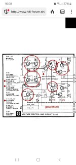
The user declared 2SA1309 (AR) , 2SA1370 (D) and 2SD1512 (AR) as problematic and replaced them. After that, the problem went away.
Unfortunately, I'm neither able to find 2SD1512 nor a replacement type. I need at least 6 pieces.
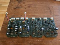
Attached is the circuit of problematic board, the service manual and 2sd1512 datasheet.
I hope a nice user here ist able to help me in this case.
Best regards
Olaf
After some time running (30-40 min), the right channel makes a loud popping noise. Then sometimes the protective circuit switches the amp off.
It's the same problem mentioned here:
http://www.hifi-forum.de/viewthread-185-10129.html (sorry, german language).
The user declared 2SA1309 (AR) , 2SA1370 (D) and 2SD1512 (AR) as problematic and replaced them. After that, the problem went away.
Unfortunately, I'm neither able to find 2SD1512 nor a replacement type. I need at least 6 pieces.
Attached is the circuit of problematic board, the service manual and 2sd1512 datasheet.
I hope a nice user here ist able to help me in this case.
Best regards
Olaf
Attachments
Have you made any voltage (circuit) or component measurements or are you just following the other user's experience?
In other words - what makes you think these transistors are the cause of your current problem?
In other words - what makes you think these transistors are the cause of your current problem?
No, not jet.
Only DC out, it was 0,4 mV and 0,9 mV.
I'm in the process of dismantling the case.
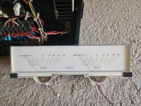
I allready fixed one cold solder joint inside the right vu meter. Now it works again (phew, no broken cool...).
The text in the linked thread describes the same effect that I experience.
First running fine, then when things warm up it makes this loud bang.
He says it's a voltage flashover within the mentioned transistors.
Next step will be measuring the voltages and see, if some parts get more hot.
Also the voltages according to the servicemanual will be checked and justified.
The power supply capacitors will be replaced, also some smaller on on the boards. The caps are 39 years old and one smaller cap bulks out (on the functional side).
I hope it won't be necessary to exchange the transistor.
I will write my findings and questions in this thread.
Thanks.
Only DC out, it was 0,4 mV and 0,9 mV.
I'm in the process of dismantling the case.
I allready fixed one cold solder joint inside the right vu meter. Now it works again (phew, no broken cool...).
The text in the linked thread describes the same effect that I experience.
First running fine, then when things warm up it makes this loud bang.
He says it's a voltage flashover within the mentioned transistors.
Next step will be measuring the voltages and see, if some parts get more hot.
Also the voltages according to the servicemanual will be checked and justified.
The power supply capacitors will be replaced, also some smaller on on the boards. The caps are 39 years old and one smaller cap bulks out (on the functional side).
I hope it won't be necessary to exchange the transistor.
I will write my findings and questions in this thread.
Thanks.
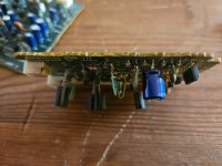
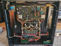
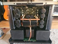
The pots for adjustments in the last pics differ a lot left versus right. Also the second power supply cap from bottom of pic has a cracked top.
I will see.
I will see.
I would consider it unlikely that the "torched" transistors return to a working state after such event - but "anything is possible" 😉First running fine, then when things warm up it makes this loud bang.
He says it's a voltage flashover within the mentioned transistors.
So keep us posted about the results after completing the first component replacement round.
Do you have a digital scope? Setting it up to a time window of e.g. 15 seconds may show you what exactly is going on (on the rails, in signal path, in the output) at the moment of the "bang".
In case you would need a 2SD1512, it can be replaced by 2SD1011 but you'll probably not be able to find it.
Another one is the 2SC3071 which is available at Digikey:
https://www.digikey.de/de/products/...-AE/12095231?s=N4IgTCBcDa4M4GMDMAGA7ARhAXQL5A
Another one is the 2SC3071 which is available at Digikey:
https://www.digikey.de/de/products/...-AE/12095231?s=N4IgTCBcDa4M4GMDMAGA7ARhAXQL5A
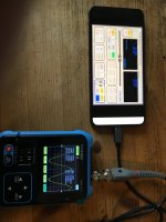

Can you set a time window fo e.g. 10 seconds on it?It's most basic, but should be sufficient.
One question (I have to learn a lot...);
In servicemanual, one has to send a 1 kHz tone for testing into the amp. They write 1 kHz, 0.5 Volt.
In my scope pic, would this be Vrms?
In servicemanual, one has to send a 1 kHz tone for testing into the amp. They write 1 kHz, 0.5 Volt.
In my scope pic, would this be Vrms?
If so then I would set it up monitoring the signal at various stages and try to capture hat happens in the moment of the "bang" a spike, jump to rail or something similar.
To eliminate the voltage amplifier board you should check what is going on on pins 4 and 5:

But before doing that I would re-solder all the voltage regulator transistors - their leads may develop cracks in their solderings that are hard to discover visiually.
Also VR151 I would check or replace as a precaution - during warming up t may also exhibit contact failure.
To eliminate the voltage amplifier board you should check what is going on on pins 4 and 5:
But before doing that I would re-solder all the voltage regulator transistors - their leads may develop cracks in their solderings that are hard to discover visiually.
Also VR151 I would check or replace as a precaution - during warming up t may also exhibit contact failure.
Depending how the signal generator is indicating it - in peak-to-peak (P2P) or rms voltage or something else.In my scope pic, would this be Vrms?
I would start with a lower amplitude - something like 0,1...0,2V.
Hey Netlist, according Copilot:In case you would need a 2SD1512, it can be replaced by 2SD1011 but you'll probably not be able to find it.
Another one is the 2SC3071 which is available at Digikey:
https://www.digikey.de/de/products/...-AE/12095231?s=N4IgTCBcDa4M4GMDMAGA7ARhAXQL5A
hFE is the amplification Parameter, right?
Expressed with the a suffix like A, R,Q,...
Is it critical when the service manual calls for, for example, ESD1512-R and I replace it with
2SC3071-Q?
Of course, I would change left and right the same.
Yes.hFE is the amplification Parameter, right?
The schematic in your first post does not call for any suffix.
So no, I would think this is not critical in this application.
The pinout of 2SC3071 should be the same as the 2SD1512 but check to make sure.
As a side note, don't trust AI for anything electronics, better compare with the datasheets. 🙂
Hugo
- Home
- Amplifiers
- Solid State
- Semi-functional Technics SE-A100, please help