Hello everyone
Ι have a question as well .
I am gathering parts for my AD1862 build after building and listening all this time to PCM1702 which i like very much
What i want to ask is about the USB/I2S card to choose . I see many of you favour Jlsounds with all the bells and whistles , i just don't see why i should spend double for my needs when i am just listening to CD quality 16bit /44.1khz at most and i am not interested in DSD or anything fancy and my current USB/I2S card is this and i cannot hear any problem .It uses the same NDK oscillators(NZ2520SDA) and seems well engineered . I know CM6631A is an old chip but it is capable of 32bit 384kHz , doesn't even need drivers for Win10 that i use , and all the modes up to 192khz that i tried are working fine. I supply 3.3v max 100mA external power via a regulated LT3042 supply and everything seems fine .
I mean will there be any improvement in sound if i choose Jlsounds or WaveIO for playing Youtube and CD ripped flac files compared to Amanero clones or Diyinhk cards like mine ?
Last edited:

@floyd89gr
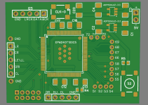
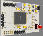
I'll receive shortly these, made by a fellow forum member.
Hope to hear some improvement, but consider this as another option
Til now, using Amanero fake with sitime clocks
I'll receive shortly these, made by a fellow forum member.
Hope to hear some improvement, but consider this as another option
Hello DiyAudio community,
TL;DR: This is a USB transport for audio output (up to 8ch) and input (2ch for now) and user device control (e.g., DSP management) from PC (MacOS/Linux/Windows) thru I2C/GPIO. Including bootloader for remote firmware update, flexible device configuration, HID interface, multiple audio output options, integration with SigmaStudio (simultanious audio playback and ADAU DSP configuration). Compact module available in USB-C and USB-B versions, isolated or non-isolated.
Latest docs, config tool, link to buy:
http://york.eclipsevl.org/...
- eclipsevl
- Replies: 274
- Forum: Vendor's Bazaar
Til now, using Amanero fake with sitime clocks
 ) because it is a new design . It seems worthy and the price is fair too .
@miro1360 quick diagnostic question to you et al.
I have your PSU1 graciously supplied complete from a forum friend here. I measure 12.5VAC verified to both sets of inputs. I can see 5VDC consistent on one output, but 0VDC on the 12V side. All components are correct and properly oriented. All four LEDs are illuminated. I suspect the regulators on the 12V side, but request any diagnostic help to get the PS going. I have your 1862 ready to go.
Thanks in advance,
Jim
Hi Jim. Leds should not light up on 12Vdc side since they are supplied with Vout from a regulator, if you measure 0V there. Can you measure vout at raw vdc (its marked as V+ and V- on the board, next to big capacitors). Pictures from underside and topside in fair quality would help.
Check soldering@miro1360 quick diagnostic question to you et al.
I have your PSU1 graciously supplied complete from a forum friend here. I measure 12.5VAC verified to both sets of inputs. I can see 5VDC consistent on one output, but 0VDC on the 12V side. All components are correct and properly oriented. All four LEDs are illuminated. I suspect the regulators on the 12V side, but request any diagnostic help to get the PS going. I have your 1862 ready to go.
Thanks in advance,
Jim
Hi Jim. Leds should not light up on 12Vdc side since they are supplied with Vout from a regulator, if you measure 0V there. Can you measure vout at raw vdc (its marked as V+ and V- on the board, next to big capacitors). Pictures from underside and topside in fair quality would help.
@Brijac that was absolutely helpful. V- to GND -16.6 and V+ to GND 16.5
Your note about the LEDs post regulator got me thinking.
Problem was the measurement at the green output screw terminals. I was measuring from the area where the terminal bites into the wire lead. When I measured from the pins protruding through the PCB from the bottom, solid readout both 5V and 12V output. I can only surmise the terminal blocks may need to be screwed down to produce a consistent measurement.
Thanks folks, will report again once I get the DAC connected up.
Ah - this interests me. I'm very ignorant of anything digital, so it's painting by numbers in my case.I used the jlsounds card in my ad1862 builds because it allows bypassing the shift registers. I built versions with shift registers and found an improvement in sound quality when I bypassed them and fed directly from the jlsounds card.
So if I used a PCM56, which are plentiful and cheap, I could connect it straight to the JLS board, yes? If that is the case I could just build the PCM56 on a piece of veroboard? I'd take the I out and connect it to a valve stage. Sounds very simple - is that right?
@andyjevans yes, right. From JLsounds or the board of @eclipsevl take the clock, dataR, dataL (dunno if pcm56 is mono or stereo) and latch (4 wires), send them to pcm56 (you need still power supply and decoupling, use Miro schematic), then with Iout you send it to the valve stage only by means of a resistor for the I/V conversion.
Simple as it gets. 😁
Simple as it gets. 😁
I've gone through my TH resistors and I've got a few to choose from:No stupid questions only stupid answers 😁
If you're going to use one pair of ic cables to the rest of that dac life, then you can calculate resistor value there as you will know the cable resistance and (main culprit) capacitance. If not, 22-47R will cover most if not all ic cables you will put there, and what it does is in short is, prevent oscillations. It also saves your opamp (potentially dac chip as well) in case of a short. Best thing is, use quality resistor there and you won't have impact on the sound, so, win win.
Holco H4 20R
Takman 33R 0.25W
Vishay MPR 47R 0.1% 0.25W
I'd go with the Holco, though I don't know if 20R is too low?
Hi @miro1360
How to reconfigure CPLD input and output pin in Quartus Prime for tda1541?
Routing with default pin (VHDL CODE) is very hard 🤣
How to reconfigure CPLD input and output pin in Quartus Prime for tda1541?
Routing with default pin (VHDL CODE) is very hard 🤣
Attachments


Finally built the PCM63 version 🙂 I-U is AD811 and Vishay Z-foil resistors.

I use it with York and reclock board, the clean side is supplied from same line as PCM63 (there is a jumper on the board).

The clocks are also on the clean side, York's are disabled. Just yesterday I realized that it would be probably better to flip York upside down, otherwise the PCB stack up is too high. But that requires the intermidiate PCB redesign.
I use it with York and reclock board, the clean side is supplied from same line as PCM63 (there is a jumper on the board).
The clocks are also on the clean side, York's are disabled. Just yesterday I realized that it would be probably better to flip York upside down, otherwise the PCB stack up is too high. But that requires the intermidiate PCB redesign.
@6L6 where did you source your one and two row x10 female pin header sockets? Anyone have an opinion about the benefits / disadvantages?Before I get too far, can anybody take a look and see if this looks right? Thank you.
View attachment 1247172
- Home
- Source & Line
- Digital Line Level
- DAC AD1862: Almost THT, I2S input, NOS, R-2R