Hello,
I'm pretty new to amp DIY, but I played around and modified some with great results, however recently I made an extremely simple prototype one stage amplifier involving just a:
1. Coupling capacitor for input
2. Single BD441 NPN transistor
3. Trimmer between the collector and base
4. Load resistor (metal film resistors I've tried from 5 to 33 Ohm)
5. Output coupling capacitor (Kemet PEG130 4mF or PEG227 2.8mF)
Load resistor is connected to the positive terminal of my car battery and then to the collector. The emitter is on the ground of the battery.
This has produced astonishing Sonic capabilities. In fact, I've never heard anything better than that and I've heard quite a few amplifiers over 10,000 Euros.
There is clipping or distortion at higher volumes, but the lower the load resistor, the more headroom without distortion. I don't know if I am going into the inactive region or saturating the transistor, but surprisingly my heatsink is very cold, whereas the load resistors heat a lot. The voltage between the transistor and load resistors is divided equally at a little over 6 volts. hopefully I won't need a second transistor in parallel, I don't know what the maximum current capability of it is, but I suppose it's fine as long as it's not too hot.
I'm writing this, because I have decided to pursue this project further, perhaps due to my lack of understanding of other designs available out there, but perhaps because I just really have never heard anything this good and I've heard a lot of amplifiers. It doesn't play very loud, but where it is playing without distortion, it is simply unbelievable. Before I proceed with everything, I thought I would ask insight in terms of what is the choke point that disallows higher volumes without distortion/clipping and any other insights in terms of design considerations. Is it because my output impedance is too high? I don't want to make it two stage or really complicate it in any way, I want to keep that purity, but insights are welcome.
The plan right now is to make low noise 300W power supply with 25V. (300VA torroid, 4 BYW29 soft recovery 10A continuous (up to 100A peak) 60ns diodes from Vishay - in full bridge, a couple of 22mF caps) I have purchased a thick aluminum chassis and have my eyes on some heat sinks, but I'm sure I will manage thermally. Again, very surprisingly, but the transistor produces very little heat, despite dividing the voltage and thus the current equally. I will make the load resistor 3 to 8 Ohms ultimately, because that's where I found the best sound quality. Many many 5W metal film resistors connected in parallel. Don't worry I won't overheat. The sound quality with these resistors is good.
If the power supply works as I hope it will, I know already that this will be not flawless, but extremely pleasant to listen to amplifier. And extremely extremely insightful. It is just crazy the level of detail that this prototype could achieve. On top of that it had super tight bass, like class D. But strings and voices - simply unparalleled.

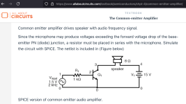
It is a basic common emitter amplifier. I may come up with a schematic, although I've never done that before. Should be doable with a pen and paper.
Download a copy of LTSpice and draw the schematic with that. You can then learn to simulate the schematic and have a lot of fun that way.
There are tutorials on youTube that can show you how to run it.
https://www.analog.com/en/resources/design-tools-and-calculators/ltspice-simulator.html
There are tutorials on youTube that can show you how to run it.
https://www.analog.com/en/resources/design-tools-and-calculators/ltspice-simulator.html
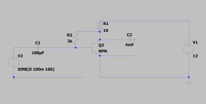
I shall try to simulate this schematic. Give me a little bit of time to learn to do it.It always helps me to see a schematic and maybe a photo.
However in practical testing and experimentation I have already found more limitations besides the maximum volume before going into clipping / distortion.
Here are the problems I found:
100uF input cap - great bass response, somewhat harsh and unrefined highs. A result of the inherent current limitations of the DAC/preAMP?
10 or 22 uF input cap - finer and more brilliant highs without harshness. (Still BJT, but much better) The bass is rolled off, not great. 10uF even messing up low female vocal notes.
Although I would love to avoid it, I guess the only solution is to introduce one more stage, probably using JFETs (to avoid high current draw at the gate thus allowing the use of smaller input caps without degrading bass performance?)
Last edited:
Not exactly, please look at the diagram I drew.Is this what you're doing?
Thank you for the suggestion.Download a copy of LTSpice and draw the schematic with that. You can then learn to simulate the schematic and have a lot of fun that way.
Does that provide clarity, sir?It always helps me to see a schematic and maybe a photo.
Attachments
You may find this amp from Nelson an inspiration to try mosfets.Hello,
I'm pretty new to amp DIY, but I played around and modified some with great results, however recently I made an extremely simple prototype one stage amplifier involving just a:
1. Coupling capacitor for input
2. Single BD441 NPN transistor
3. Trimmer between the collector and base
4. Load resistor (metal film resistors I've tried from 5 to 33 Ohm)
5. Output coupling capacitor (Kemet PEG130 4mF or PEG227 2.8mF)
Load resistor is connected to the positive terminal of my car battery and then to the collector. The emitter is on the ground of the battery.
This has produced astonishing Sonic capabilities. In fact, I've never heard anything better than that and I've heard quite a few amplifiers over 10,000 Euros.
There is clipping or distortion at higher volumes, but the lower the load resistor, the more headroom without distortion. I don't know if I am going into the inactive region or saturating the transistor, but surprisingly my heatsink is very cold, whereas the load resistors heat a lot. The voltage between the transistor and load resistors is divided equally at a little over 6 volts. hopefully I won't need a second transistor in parallel, I don't know what the maximum current capability of it is, but I suppose it's fine as long as it's not too hot.
I'm writing this, because I have decided to pursue this project further, perhaps due to my lack of understanding of other designs available out there, but perhaps because I just really have never heard anything this good and I've heard a lot of amplifiers. It doesn't play very loud, but where it is playing without distortion, it is simply unbelievable. Before I proceed with everything, I thought I would ask insight in terms of what is the choke point that disallows higher volumes without distortion/clipping and any other insights in terms of design considerations. Is it because my output impedance is too high? I don't want to make it two stage or really complicate it in any way, I want to keep that purity, but insights are welcome.
The plan right now is to make low noise 300W power supply with 25V. (300VA torroid, 4 BYW29 soft recovery 10A continuous (up to 100A peak) 60ns diodes from Vishay - in full bridge, a couple of 22mF caps) I have purchased a thick aluminum chassis and have my eyes on some heat sinks, but I'm sure I will manage thermally. Again, very surprisingly, but the transistor produces very little heat, despite dividing the voltage and thus the current equally. I will make the load resistor 3 to 8 Ohms ultimately, because that's where I found the best sound quality. Many many 5W metal film resistors connected in parallel. Don't worry I won't overheat. The sound quality with these resistors is good.
If the power supply works as I hope it will, I know already that this will be not flawless, but extremely pleasant to listen to amplifier. And extremely extremely insightful. It is just crazy the level of detail that this prototype could achieve. On top of that it had super tight bass, like class D. But strings and voices - simply unparalleled.
It's a slow day. Time for a little entertainment - a micro project!
Someone sent me a request for a simple 1 watt amplifier.
How could I resist?
My answer:
Assuming that your preamp can put out 2 volts (and it should),
a 1 watt design would be the easiest thing in the world.
Attached is an example.
I will put it up on the Pass Labs forum at diyaudio and see
what kind of suggestions it gets for construction and improvement.
Feel free to post questions.
"Zen Mod" will likely be the first to take the bait.
The following draws 1.5A off a 19V computer desktop supply and gets
1...
- Nelson Pass
- Replies: 308
- Forum: Pass Labs
That is very simple, but dc through the voice coil is bad idea. Normally dc on output should be minimal, just few millivolts.Is this what you're doing?
This circuit heats up the speaker voice coil and forces it out of optimal position by design. Not suitable for true classA amp.
Nice, I was going to try something very similar with MOSFETs after making it work with BJTs. Try a circuit like you provided and then move on to explore further the various things in this thread https://www.diyaudio.com/community/...-build-class-a-single-mosfet-amplifier.368606You may find this amp from Nelson an inspiration to try mosfets.
It's a slow day. Time for a little entertainment - a micro project!
Someone sent me a request for a simple 1 watt amplifier.
How could I resist?
My answer:
Assuming that your preamp can put out 2 volts (and it should),
a 1 watt design would be the easiest thing in the world.
Attached is an example.
I will put it up on the Pass Labs forum at diyaudio and see
what kind of suggestions it gets for construction and improvement.
Feel free to post questions.
"Zen Mod" will likely be the first to take the bait.
The following draws 1.5A off a 19V computer desktop supply and gets
1...
- Nelson Pass
- Replies: 308
- Forum: Pass Labs
Maybe I should already assemble something closer to what you provided for the simple MOSFET amp for my simple BJT amp, because I'm running into issues that I have described, but still failed to diagnose. Maybe adjusting the bias connected straight to the positive rail as well as at the collector would make it easier to operate linearly and not clip anywhere regardless of my load resistance. I'm still playing with the simulation trying to figure it out.
Getting my heatsinks and chassis soon as well that should be able to handle up to 200W or so of class A. Not that I need that at first.
I am not sure why you have issues with such simple circuit. There is not much which can go wrong. As long as you provide proper bias for low distortion, it should work just fine.
Have you measured distortion of your amplifier at 1watt? I expect it to be few percent. Ideally you should measure % distortion vs current to optimize it.
Have you measured distortion of your amplifier at 1watt? I expect it to be few percent. Ideally you should measure % distortion vs current to optimize it.
Well, I would need to get an oscilloscope first, but based on listening experience, I run into clipping and distortion as early as -20dB of my DAC preamp output (1vrms) on busier tracks. Using a lower load impedance like 5 ohm instead of 10 ohm, extends the headroom, but I don't understand why. I don't know if the waveform is a beautiful sine either. It does sound amazing in some ways. I'm trying to find out what causes the clipping especially with higher load impedance so that I could find solutions and adjust the circuit accordingly.
You do not need oscilloscope. Its very hard to see distortion, besides, its not numerical.
All you need is laptop or PC with soundcard. For this circuit even soundcard is not needed. Every laptop has mic/line level input. Use REW or RightMark software, both are free. Plenty of threads to show you how.
You need to see what harmonic spectrum you are generating.
All you need is laptop or PC with soundcard. For this circuit even soundcard is not needed. Every laptop has mic/line level input. Use REW or RightMark software, both are free. Plenty of threads to show you how.
You need to see what harmonic spectrum you are generating.
I have been using the excellent and free software package called REW and a sound interface card (or DAC/ADC) to measure my amps for years now. It’s fast, easy and really costs nothing if you have a sound interface already. REW is normally used for measurement of speakers with microphones, however, it’s interface, GUI, and math engine are top-notch and lend themselves to an excellent amp measurement tool. I have been asked numerous times via PM’s to assist DIYA members make their own measurement setup using REW. Recently, I was asked again in the M2X thread when I chimed in...
- xrk971
- Replies: 1,965
- Forum: Software Tools
@adason The amp is constantly consuming 10 watts and my output voltage is swinging around -6.5V to +6.5V. I would damage my PC circuitry if I measured that. For starters I can measure the low voltage output and see if I get any clues, but that's not where the problem occurs.
The description says:
"For measurements of amp power up to 1w (8Vpp) it’s ok to connect the dummy load to your sound card directly. However, if your amp ever had a burp and hits the interface input preamp with too much voltage it can fry the input stage. I would recommend adding a ~10:1 voltage divider using a 20k and 2k resistor and taking the middle node attenuated output as the signal to your sound interface."
I can connect 20k + 2k resistors. Do I understand correctly that I would connect them in series and connect my positive lead going into the sound card to the middle node between them while connecting the negative lead to the ground?
Attachments
- Home
- Amplifiers
- Solid State
- Extremely simple class A SE amp