Hello DIY Audio enthusiasts,
I am excited to share my latest project: ESP32_DSP. It is a digital signal processing solution built around the powerful ESP32 microcontroller, designed for audio enthusiasts who want to explore flexible and affordable audio filtering.
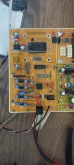
This project integrates a DIR9001 (digital audio receiver) for input, an ESP32 for real-time DSP processing, and a TDA1387 DAC for output. It supports a variety of filters such as low pass, high pass, band pass, notch, peak, low pass, and high pass, offering great flexibility for various audio applications.
While I am confident in the design and functionality, I would like to ask the professionals and experienced members of this community: Is this approach suitable for achieving high-quality audio performance, or will ready-made DSP boards from Aliexpress do a better job?
I would love to hear your suggestions, ideas, and ideas for improvement. Whether you're a seasoned audio DIYer or just starting out, feel free to share your thoughts and questions.
Thank you and I look forward to learning from your insights!
https://github.com/Kristian8606/ESP32_DSP/tree/main
I am excited to share my latest project: ESP32_DSP. It is a digital signal processing solution built around the powerful ESP32 microcontroller, designed for audio enthusiasts who want to explore flexible and affordable audio filtering.
This project integrates a DIR9001 (digital audio receiver) for input, an ESP32 for real-time DSP processing, and a TDA1387 DAC for output. It supports a variety of filters such as low pass, high pass, band pass, notch, peak, low pass, and high pass, offering great flexibility for various audio applications.
While I am confident in the design and functionality, I would like to ask the professionals and experienced members of this community: Is this approach suitable for achieving high-quality audio performance, or will ready-made DSP boards from Aliexpress do a better job?
I would love to hear your suggestions, ideas, and ideas for improvement. Whether you're a seasoned audio DIYer or just starting out, feel free to share your thoughts and questions.
Thank you and I look forward to learning from your insights!
https://github.com/Kristian8606/ESP32_DSP/tree/main

ello DIY Audio enthusiasts,
I am excited to share my latest project: ESP32_DSP. It is a digital signal processing solution built around the powerful ESP32 microcontroller, designed for audio enthusiasts who want to explore flexible and affordable audio filtering.
This project integrates a DIR9001 (digital audio receiver) for input, an ESP32 for real-time DSP processing, and a TDA1387 DAC for output. It supports a variety of filters such as low-pass, high-pass, band-pass, notch, peak, low-plate, and high-plate, offering great flexibility for various audio applications.
Although I am confident in the design and functionality, I would like to ask the professionals and experienced members of this community: Is this approach suitable for achieving high-quality audio performance or will ready-made DSP boards from Aliexpress do a better job?
I would love to hear your suggestions, ideas, and ideas for improvement. Whether you are a seasoned audio DIYer or just starting out, feel free to share your thoughts and questions.
Thank you and I look forward to learning from your insights!
https://github.com/Kristian8606/ESP32_DSP/tree/main
Englih please
dave

diyAudio moderation team
Sorry for the delay. I plan to make an esp32 as well as a dac on one board. I will add several esp32s to one i2s bus to try to create 6 channels. The idea is for one esp32 to serve as a DSP and process the signal, and then three others to split it into low, medium and high. I have not tested such a configuration yet and I do not know how stable multiple devices to one i2s bus will be.


ESP32 notice: ESP32 blocks when the WiFi demands it. It causes I/O jitter. There is a library functions to silence wifi when it is not needed.
Why do you need the spdif from the DIR ? ESP32 has his own i2s , are you afraid that the MCKL signal will not be as good as from the DIR ? DSP is fine ok but when splinting the signal than after that you will need 3 amps for all of the frequencies . Probably, if you want to use it as a DSP , split the HF only this way will be easier for you and for the next stage into your equipment . What i`m thinking to use this controller is a transport and probably a digital volume control , but i have not came to any viable solution at the output stage .... Also i have some digital filters like SM5803 to experiment , but at the moment i`m lacking in time ...
I use a dir9001 to receive audio from my airport or other sound source, I don't even use MCLK. by the way I managed to synchronize 4 esp32s3, using one for EQ sound processing as the initial stage + volume control. In the next stage, the remaining three esp32s3 receive the signal and process it with FIR filters for low mid and high. One esp32s3 manages to process up to 1500 taps. It is currently playing as a test and I am trying to correct and minimize a hum around 100 hertz probably caused by the power supply. But the sound of a crossover built with FIR filters is unique to me.
Не съм сигурен за моя аматьорски осцилоскоп, но измервам 27 миливолта пик до пик при 120 херца с работещ DAC. Когато направя пауза DAC-а сякаш се забавя и честотата пада до 40-50 херца. Ще трябва да разбера какво става, ако някой е имал опит, моля да сподели опита си. Трите ЦАП-а отиват директно към шестте канала на усилвателя. Никога не съм имал такъв проблем с DAC и аналоговия кросоувър.
What the output of your dac looks like ? Is this an R2R output ? If so maybe some resistors there are not valued correctly . Let me give you one shot of the DF which i use at the moment , the one ready 🙂 SMP5803 are for another board with TDA1547 , but the board is not sent yet 🙁
Attachments
These are esp32s3 for performing DSP processing with the esp-dsp library. The DACs around the board are ProtoDac x8 tda1387, one for each channel. Even though I'm testing with so many cables, I managed to minimize the noise from the power supply, but the low-frequency hum does not disappear. This is probably noise from the DACs and I need to figure out how to eliminate this noise.
Are you sure if it is not a noisy PSU ? 50-60 HZ is general power supply noise .. Also do you have decoupling capacitors close to the power rails ?
I generally doubt everything, but the fact that when I play music the jitter frequency is around 100 hertz, but when I pause it the frequency drops to around 47-50 hertz, makes me think that some DAC is causing it.
The power supply is smps, I will replace it with a linear one and see if there is an improvement. I am also not sure if I should connect the GND of the amplifier to the GND of the DAC, or the ground from the cinches is quite enough.
Remove the SMPS ! and never use those for audio 🙂 Chinch ground should be enough . ANd yes this DAC chip is very sensitive to power line noise , have you used capacitors near all of the power lines near it ?
I had no problem with this power supply when I used a DAC and an analog crossover. But I removed the analog crossover to replace it with an esp-dsp. Now my amplifier has no preamp, only a 10K potentiometer to adjust the volume while testing.
Ok crossover is gone , but what about the pre-am section ? Have you removed your pre-amp also ? Do you have other sources to check if the amp is operating like it should , etc input impedance should be around 47 k ?
In the past, my amplifier has worked without a crossover with just three stereo 10k potentiometers on each channel. Naturally I used two channel for stereo, but I designed it with 6 channels for tri-amping. How do I measure the output impedance of a DAC?
Measuring the output impedance of a DAC (Digital-to-Analog Converter) can be a bit technical, but here's a straightforward method you can follow:
Where RloadR_{load} is the value of the load resistor.
For example, if Vno_loadV_{no\load} is 1V and VloadV{load} is 0.8V with a 1 kΩ resistor, the output impedance would be:
Take with consideration , taken from an AI - I`m using dac`s with known parameters so never done that... But if there is an issue only with one DAC , have a look at the power source of it , if it using resistance ladder output, do you use decoupling cap ?
- Generate a Test Tone: Play a steady test tone, such as 1 kHz, from the DAC.
- Measure the Output Voltage Without Load: Use a multimeter to measure the AC output voltage of the DAC without any load connected. Let's call this voltage Vno_loadV_{no\_load}.
- Add a Load Resistor: Connect a known resistor (e.g., 1 kΩ) across the DAC output. This resistor should be of a value comparable to the expected output impedance of the DAC.
- Measure the Output Voltage With Load: Measure the AC output voltage again with the load resistor connected. Let's call this voltage VloadV_{load}.
- Calculate the Output Impedance: Use the following formula to calculate the output impedance ZoutZ_{out}:
Where RloadR_{load} is the value of the load resistor.
For example, if Vno_loadV_{no\load} is 1V and VloadV{load} is 0.8V with a 1 kΩ resistor, the output impedance would be:
Take with consideration , taken from an AI - I`m using dac`s with known parameters so never done that... But if there is an issue only with one DAC , have a look at the power source of it , if it using resistance ladder output, do you use decoupling cap ?
- Home
- Source & Line
- Digital Line Level
- Esp32_DSP