A cable tracer, also known as a wire tracer or tone generator and probe, is a tool used to identify and trace wires or cables within a network or electrical system. It's particularly useful for pinpointing the location of specific wires, troubleshooting issues, and ensuring proper connections.
Depending on the purpose, you can trace the exact path followed by the conductor, or just locate its destination (end point), or both.
Two main principles are usable: electrostatic or magnetic. Each has a specific domain of application, and in addition, a hybrid, electromagnetic mode is also possible. It is rarely encountered commercially, but Tracy includes it, and it has the ability to solve normally intractable problems.

For cheap instruments, the generator is just an audio device generating an easily recognizable musical jingle, rich in high frequencies.
For a more accurate pinpointing, a differential operation is preferable:

The single-ended electrostatic mode is very cheap and has a wide detection area (too wide!), and the differential mode is very restrictive (too restrictive!).
They are useful though.
This is the 100KHz transmitter:

And here is the (kludgy!) receiver:

Depending on the purpose, you can trace the exact path followed by the conductor, or just locate its destination (end point), or both.
Two main principles are usable: electrostatic or magnetic. Each has a specific domain of application, and in addition, a hybrid, electromagnetic mode is also possible. It is rarely encountered commercially, but Tracy includes it, and it has the ability to solve normally intractable problems.
How It Works:
- Components:
- Transmitter (Tone Generator): This part is connected to the wire or cable you want to trace. It sends a signal (often an audible tone) down the wire.
- Receiver (Probe): This handheld device detects the signal emitted by the transmitter. When it gets close to the wire carrying the signal, it produces an audible or visual indication.
- Operation:
- Connecting the Transmitter: Attach the transmitter to the wire or cable using clips or a specific connector.
- Activating the Transmitter: Turn on the transmitter to start sending the signal.
- Using the Receiver: Move the receiver along the path where you suspect the wire is located. The closer you get to the wire, the stronger the signal or tone you will hear.
For cheap instruments, the generator is just an audio device generating an easily recognizable musical jingle, rich in high frequencies.
For a more accurate pinpointing, a differential operation is preferable:
The single-ended electrostatic mode is very cheap and has a wide detection area (too wide!), and the differential mode is very restrictive (too restrictive!).
They are useful though.
This is the 100KHz transmitter:
And here is the (kludgy!) receiver:
Attachments


First, here is the transmitter: it is extremely simple, and could be built in many other ways. I have heaps of 2MHz crystals, which is why I used one here.
A baseband oscillator would work as well, as would any solution outputting 100KHz.


The output capacitor is a X-rated type, to allow a direct connection to the mains when required. In the same spirit the case is fully insulated. You sometimes need to trace live connections
A baseband oscillator would work as well, as would any solution outputting 100KHz.
The output capacitor is a X-rated type, to allow a direct connection to the mains when required. In the same spirit the case is fully insulated. You sometimes need to trace live connections
Now, the interesting part: the receiver.
It has very unusual features, giving it almost super-natural performances.
Here is the first part:

The front-end is especially unusual: it is a differential amplifier based on the Rush topology, and it is bootstrapped. The purpose is to make the whole circuit "float" in common-mode, in order to suppress parasitic unbalanced to balanced conversion.
In a regular differential, if a signal is applied to one of the inputs with the other left floating, some amplification will take place because the bias circuit and parasitic capacitance will act as an implicit ground.
This is a problem because in differential mode, you want to detect a true differential excitation only, The advantage of the differential mode is the very good pinpointing accuracy, but without the parasitic ground suppression, the detection would be blurred and cover a much larger area.
The receiver can also work in the more traditional manner, by using a probe having the - input and the ground tied together. Magnetic sensing is also possible thanks to an inductive probe.
Here is the rest of the receiver:

It is a VCO converting the signal strength into a variable pitch and a small voltage regulator.
This is the kludge:

And these are the pluggable probes:

It has very unusual features, giving it almost super-natural performances.
Here is the first part:
The front-end is especially unusual: it is a differential amplifier based on the Rush topology, and it is bootstrapped. The purpose is to make the whole circuit "float" in common-mode, in order to suppress parasitic unbalanced to balanced conversion.
In a regular differential, if a signal is applied to one of the inputs with the other left floating, some amplification will take place because the bias circuit and parasitic capacitance will act as an implicit ground.
This is a problem because in differential mode, you want to detect a true differential excitation only, The advantage of the differential mode is the very good pinpointing accuracy, but without the parasitic ground suppression, the detection would be blurred and cover a much larger area.
The receiver can also work in the more traditional manner, by using a probe having the - input and the ground tied together. Magnetic sensing is also possible thanks to an inductive probe.
Here is the rest of the receiver:
It is a VCO converting the signal strength into a variable pitch and a small voltage regulator.
This is the kludge:
And these are the pluggable probes:
Here is a formal, summary description of the circuits.
The transmitter doesn't need lots of explanation: it is just an ordinary Colpitts oscillator followed by two digital dividers: the first divides by ten, and the second by two, to arrive at a symmetrical 100KHz squarewave.
This 100KHz is buffered and protected by diodes and a Transil across the battery, to prevent involuntary charging when the device is connected to the mains or any other high voltage AC.
No rocket science, but it works.
The receiver is somewhat more complicated, starting with the Rush front-end, and its cross-connected bootstraps.
This configuration cancels the effect of the ghost GND inherent to the circuit, by making the "neutral" potential of each side equal to that of the opposite input. This means that no current can flow through the Rush, unless it originates from a true differential signal between the bases of the input transistors.
After the front-end, a tuned amplifier based on Q5 and Q6 increases the available gain.
A crystal filter follows (Q7), but in between is a first AGC (M1), controlled by the final output voltage. C13/14 cancel the parallel capacitance of the tiny crystal, visible in the center of this pic:

Just behind, the adjustable capacitor is just visible.
A JFET buffer follows, and R26 is the potentiometer for manual gain adjustement helped by the second AGC, M2.
Finally, a gain block composed of Q8, M3, M4 brings the level to its final value.
Two prebiased diode detectors D2 D4 D5 D6 recover the detected voltage. The lower detector also provides the RSS to the VCO.
The VCO is based on slightly manipulated CD4046 PLL, and the 6V regulated supply is quite ordinary. The zener D2 allows self-starting
The transmitter doesn't need lots of explanation: it is just an ordinary Colpitts oscillator followed by two digital dividers: the first divides by ten, and the second by two, to arrive at a symmetrical 100KHz squarewave.
This 100KHz is buffered and protected by diodes and a Transil across the battery, to prevent involuntary charging when the device is connected to the mains or any other high voltage AC.
No rocket science, but it works.
The receiver is somewhat more complicated, starting with the Rush front-end, and its cross-connected bootstraps.
This configuration cancels the effect of the ghost GND inherent to the circuit, by making the "neutral" potential of each side equal to that of the opposite input. This means that no current can flow through the Rush, unless it originates from a true differential signal between the bases of the input transistors.
After the front-end, a tuned amplifier based on Q5 and Q6 increases the available gain.
A crystal filter follows (Q7), but in between is a first AGC (M1), controlled by the final output voltage. C13/14 cancel the parallel capacitance of the tiny crystal, visible in the center of this pic:
Just behind, the adjustable capacitor is just visible.
A JFET buffer follows, and R26 is the potentiometer for manual gain adjustement helped by the second AGC, M2.
Finally, a gain block composed of Q8, M3, M4 brings the level to its final value.
Two prebiased diode detectors D2 D4 D5 D6 recover the detected voltage. The lower detector also provides the RSS to the VCO.
The VCO is based on slightly manipulated CD4046 PLL, and the 6V regulated supply is quite ordinary. The zener D2 allows self-starting
Application:
First, unbalanced electrostatic mode:
It is the most commonly used mode for simple cable-tracers, and it is the easiest to apply and setup.
The transmitter is connected between the cable to be tested and the ground, or something similar: it could be a true earth, a big metallic mass, a metal pipe or anything large enough and conducting.
The receiver is fitted with the SE probe, and used to explore the possible space.
It works rather well in simple situations, but there is a major snag:
As soon as cables run along each other for more than a meter or so, the capacitive crosstalk becomes a major problem: basically, all the cables in the bundle or harness react almost identically, making an accurate identification difficult.
To alleviate the problem, Tracy is fitted with a retractable shield.
Here, it is shown fully retracted, exposing the totality of the sensing probe:

Here, it is completely extended, covering the whole probe area except for the front window (the aluminized paper will be explained later):

This is the front area:

The cover shield acts as a "focal" control: when it is fully retracted, the sense volume is half of a sphere, but when it is fully extended, the detection zone is reduced to a fraction of steradian.
This goes some way into improving the detection sharpness.
During the first exploration phase, you use the wide mode to detect broadly the area of interest, and when it is done, you search more accurately in narrow mode.
It is not a panacea, and the zone of interest remains fuzzy, but it is better than nothing.
It is possible to do much better, as we will see later.
Note that the sensing tips don't need to be naked: they can be covered with an insulating sleeve without affecting the performance of the capacitive sensing: in risky environments, where an accidental contact could be problematic, it could be of a great help
First, unbalanced electrostatic mode:
It is the most commonly used mode for simple cable-tracers, and it is the easiest to apply and setup.
The transmitter is connected between the cable to be tested and the ground, or something similar: it could be a true earth, a big metallic mass, a metal pipe or anything large enough and conducting.
The receiver is fitted with the SE probe, and used to explore the possible space.
It works rather well in simple situations, but there is a major snag:
As soon as cables run along each other for more than a meter or so, the capacitive crosstalk becomes a major problem: basically, all the cables in the bundle or harness react almost identically, making an accurate identification difficult.
To alleviate the problem, Tracy is fitted with a retractable shield.
Here, it is shown fully retracted, exposing the totality of the sensing probe:
Here, it is completely extended, covering the whole probe area except for the front window (the aluminized paper will be explained later):
This is the front area:
The cover shield acts as a "focal" control: when it is fully retracted, the sense volume is half of a sphere, but when it is fully extended, the detection zone is reduced to a fraction of steradian.
This goes some way into improving the detection sharpness.
During the first exploration phase, you use the wide mode to detect broadly the area of interest, and when it is done, you search more accurately in narrow mode.
It is not a panacea, and the zone of interest remains fuzzy, but it is better than nothing.
It is possible to do much better, as we will see later.
Note that the sensing tips don't need to be naked: they can be covered with an insulating sleeve without affecting the performance of the capacitive sensing: in risky environments, where an accidental contact could be problematic, it could be of a great help
Balanced, E-mode:
When the connection to be traced is symmetrical, this mode is possible and has the advantage of an excellent pinpointing accuracy; conversely, the detectable distance is very short.
A good balanced connection has a good immunity to perturbations, both for egress and ingress, making the detection difficult.
Tracy has a huge reserve of gain available, thanks to its very narrow detection bandwidth, meaning it is still workable, but for a vast area it is time-consuming.
To use this mode, connect the transmitter between the a and b pair, floating, and use the balanced probe on the receiver
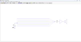
Magnetic detection
Magnetic tracing is quite different from the E methods:
First of all, you need to know the location of end points beforehand: since you need to pass a current through the cable being traced, you have to apply a short at the remote side.
Thus, this method allows you to follow the path of the cable but nothing else. The other methods allow you to discover the path or the terminating point of a cable, or both.
The test setup looks like this:

L1 is the magnetic probe
The current provided by Tracy cannot exceed a few tens of mA, which is meagre compared to commercial tracers: they use an excitation current of up to 1 ampere or even more, but this poses no problem: the sensitivity and selectivity of the receiver more than compensate this weakness.
You can perfectly detect a cable buried 1.5m below the surface of a sidewalk.
For this application, the aluminised paper can begin to play a role: if for some reason, a parasitic E-field is created by the configuration, it can be blocked by obturating the sensing window with this paper, which is composed of carbon, aluminum, and was used in cheap electroprinters.
It is now completely obsolete, but it has the remarkable properties of being perfectly transparent for H fields, and completely opaque for E fields.
Ideally, the forward and return paths of the test current should be well separated, to avoid their mutual cancellation: the CUT and ground is ideal, but even a pair leaks a little signal when you have no other option
Magnetic tracing is quite different from the E methods:
First of all, you need to know the location of end points beforehand: since you need to pass a current through the cable being traced, you have to apply a short at the remote side.
Thus, this method allows you to follow the path of the cable but nothing else. The other methods allow you to discover the path or the terminating point of a cable, or both.
The test setup looks like this:
L1 is the magnetic probe
The current provided by Tracy cannot exceed a few tens of mA, which is meagre compared to commercial tracers: they use an excitation current of up to 1 ampere or even more, but this poses no problem: the sensitivity and selectivity of the receiver more than compensate this weakness.
You can perfectly detect a cable buried 1.5m below the surface of a sidewalk.
For this application, the aluminised paper can begin to play a role: if for some reason, a parasitic E-field is created by the configuration, it can be blocked by obturating the sensing window with this paper, which is composed of carbon, aluminum, and was used in cheap electroprinters.
It is now completely obsolete, but it has the remarkable properties of being perfectly transparent for H fields, and completely opaque for E fields.
Ideally, the forward and return paths of the test current should be well separated, to avoid their mutual cancellation: the CUT and ground is ideal, but even a pair leaks a little signal when you have no other option
And finally:
Electromagnetic detection:
Some cases are not covered by the scenarii described previously.
What if you need to trace an unknown cable, covered in some sort of shield? it could be armoured, shielded, covered in lead, etc. Even if the initial purpose is water-proofing or mechanical toughness, not electrostatic shielding, that will be the result anyway.
The shielding will block electrostatic detection methods, and if you don't know where its termination is, you cannot short it to use magnetic detection.
Thus, no solution?
With Tracy, there is always a solution: it operates at 100kHz, which is pretty high for this type of gear: most commercial detectors operate in the region of 10kHz.
At 100kHz, higher order effects begin to appear: the cable you test is going to behave like a "long wire" antenna, and antenna means antenna current.
This current is detectable, even through lead or any other shield.
Thus, what you need to do is to connect the transmitter in single-ended E mode to the conductor plunging into the mystery of a buried lead-covered cable with an unknown destination. You then follow the cable with the magnetic probe. You may not be able to follow it to the very end, because the antenna current decreases with the distance, but you will arrive close to some kind of telecom infrastructure, and chances are that the termination sits there.
As in all magnetic detection cases, parasitic E-mode perturbations can appear. To filter them out, and detect the magnetic field only, use the "magic" printing paper to cover the probe and the detection window
Unusual and original Tx/Rx interfaces
Tracy is not limited to cables or pairs: it can also help trace and locate other types of objects. What about hydraulic pipes concrete rebars, etc?
In fact, anything conducting can be traced, you just need to find a way to inject the stimulus.
Here are some ideas:

From left to right you have a DIY spring clamp with a ferrite clamp-on interference arrester glued on, a micro-coax with its center conductor partially exposed, and a pair of ferrite U-core from TV horizontal unit.
Here are the same with the windings visible:

When the winding is connected to the transmitter, it induces a voltage into the pipe or the rebar, and if the circuit is closed, it generates a current detectable by the magnetic probe of Tracy's receiver.
This allows you to trace a particular pipe in a hydraulic machine.
The pigtail from the coaxial can be shortened, to 1mm, to be able to pinpoint accurately a unique conductor in a cramped space
Tracy is not limited to cables or pairs: it can also help trace and locate other types of objects. What about hydraulic pipes concrete rebars, etc?
In fact, anything conducting can be traced, you just need to find a way to inject the stimulus.
Here are some ideas:
From left to right you have a DIY spring clamp with a ferrite clamp-on interference arrester glued on, a micro-coax with its center conductor partially exposed, and a pair of ferrite U-core from TV horizontal unit.
Here are the same with the windings visible:
When the winding is connected to the transmitter, it induces a voltage into the pipe or the rebar, and if the circuit is closed, it generates a current detectable by the magnetic probe of Tracy's receiver.
This allows you to trace a particular pipe in a hydraulic machine.
The pigtail from the coaxial can be shortened, to 1mm, to be able to pinpoint accurately a unique conductor in a cramped space
I don't understand enough to comment on this project, but thanks for sharing and congrats with such a nice DIY effort.
Hugo
Hugo
Little to understand: it is just transformer's theory extended and generalized. A transformer is not limited to EI or toroidal: it can assume any shape or formI don't understand enough to comment on this project
The versatility and performances of the basic Tracy are exceptional, but it is possible to go well beyond by combining the modes of operation.
Here is an example (real life inspired):
In a street cabinet, you find an "orphaned" pair: one that is undocumented and unused. You would like to use it, but first you need to know its quality, and where its other end is terminated.
First, you connect the transmitter in unbalanced mode, to the shorted pair.
You go to the Central Office and find the MDF room. There you find yourself in front of a behemoth of a distribution frame: meters long, a wall of Siemens connection blocks, and thousand upon thousand of termination points.
At first sight, finding your pair in this mass is like finding a needle in the proverbial haystack.
The receiver of Tracy is fitted with the unbalanced probe, its gain is pushed to the max, and the cover is fully retracted, in wide mode.
Immediately, when you enter the room, the receiver already reacts. Guided by the pitch, you converge towards an area of the MDF. There, you progressively reduce the gain and change the focal to "narrow" mode.
In the end, you locate an area of a fraction of a square meter where your pair ends, but you cannot be more accurate in this mode, and the area of interest comprises a few hundred pairs.
You return to the street cabinet, and connect the transmitter in balanced mode.
Back to the MDF, with the receiver fitted with the balanced probe you sweep the area you had previously earmarked.
In a matter of seconds, Tracy squeaks on a pair: that's it, you have found it, and it only took a few minutes.
The most annoying part is the back and forth trip between the street and the CO, but if you leave a colleague at the street cabinet, he can change the connection mode when you instruct him to do so
One more point: I have chosen the 100kHz frequency for good reasons: it is high enough to be easily detectable at a distance, without suffering too much attenuation on long distances.
It is a good trade-off, but opting for such a round frequency figure can be problematic: there are huge numbers of various equipments using frequencies that are multiple or submultiple or harmonically related to 100kHz, and it could result in unwanted interferences.
I didn't encounter such issues, but the tests I made were limited and for a regular use, it could become a problem.
If you build your version, I advise you use a slightly offset value, like 101.234kHz or 99.876 kHz. The exact value doesn't matter, as long as it doesn't match a commonly used frequency
- Home
- Design & Build
- Equipment & Tools
- Here is Tracy, the trenchant cable-tracer