Hello,
I remember an even lower value than 0,5 uF did crank up dc voltage in one of builds.
I think you should parts that can stand the " abuse ". Of course you should use psud before you will doubt my ideas haha. I only used such a cap if i did not get enough dc voltage when i should have used a different transformer.
Greetings Eduard

If you have a input cap because you skimped on proper choke it's not a choke input. Also any step up/step down power trans is a nono in serious audio but good enough for Diy audio 🙂Hi! This is my very first post here. I'm so grateful for all the tips and ideas I've found here over the years, so I hope this post might give a little bit back.
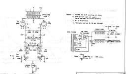
I just finished a monoblock build of 2A3-40:s in push pull fixed bias, with a parallel coupled 5687 as input and driver, via a Tamura A-351 interstage and splitter. The power supply is choke input with a 8H 250 mA choke, but preceded by a small 0.5 uF 1500V PIO cap. Smoothing caps are one 100uF for the output, and two more for the input, all motor run caps.
I run the output tubes at 305V and about 65mA.
The sound is so powerful it's almost scary! It must be because of the choke input power supply, which I truly recommend. All iron is vintage from Japan, which means I use a step down transformer to power them here in Swden, but it works great!
Of course I only do totally unserious audio and it sounds like crap, thanks for the encouragement! 😉
The 20H 100mA choke, 10H 150mA choke and the 5H 200mA chokes I have been using work fine.
They do not vibrate, are not noisy, do not get hot, etc.
Perhaps they would vibrate if they were mounted on a magnetic steel chassis.
They work well with center tapped secondaries and solid state full wave rectifiers, without any input capacitors.
The power transformers I use run much cooler with choke input filters too.
Limono,
You said:
"Also any step up/step down power trans is a nono in serious audio but good enough for Diy audio"
A few Hi Fi fans might disagree . . .
A utility company power pole with a big transformer on it, is right outside their house.
That step down transformer, steps 12kV down to the 2-phase 120VAC plus 120VAC that runs their house.
What makes a quality step-up or step-down transformer in your house ruin the Hi Fi?
It merely matches 100V Japan power, 120V US power, 220V / 240V European / Australian power to work with . . .
Hi Fi gear that is manufactured to work with a voltage that is only available in another part of the world.
Hello,
Electricity meter on a pole in open air in Laos.
Amorphous core big transformer in Central Vietnam.
So no need to worry about an extra transformer.
If the 0,5 cap is only there to " protect" other parts you could try reducing it to make it more choke input.
I have used Tango chokes designed for choke input but the Lundahl ones were better.
Greetings Eduard
I use them myself no offense- with a sources. I wouldn't use them with an amp. If Japan Iron is used for 100V , bucking transformer works fine in US where you see 125V at most. If you can match the power ratings of Utility trans I see no problemLimono,
You said:
"Also any step up/step down power trans is a nono in serious audio but good enough for Diy audio"
A few Hi Fi fans might disagree . . .
A utility company power pole with a big transformer on it, is right outside their house.
That step down transformer, steps 12kV down to the 2-phase 120VAC plus 120VAC that runs their house.
What makes a quality step-up or step-down transformer in your house ruin the Hi Fi?
It merely matches 100V Japan power, 120V US power, 220V / 240V European / Australian power to work with . . .
Hi Fi gear that is manufactured to work with a voltage that is only available in another part of the world.
limono,
I have used Buck and Boost transformers around the world.
They are good enough for 'Government Work', and good enough for 'High End Audio'.
Quality parts + Quality engineering + Quality manufacturing = Quality Results.
parts, engineering designs, manufacturing procedures . . . it only takes one of those that is not quality, that gives Bad Results.
Weakest Link is not a theory, it has been proven.
The first Tacoma Narrows Bridge, look for that very old video (they used Film back then).
My two cents: Good power transformers for tube amps are expensive and not very easy to find. Adjusting the mains voltage with a stepdown transformer is probably a small price to pay to be able to use good quality vintage iron. Any percieved sonic consequenses are probably miniscule compared to the room acoustics😎
The variable inductance is there in Class C and Class B amplifiers to ensure that the choke input power supply continues to operate in that mode when the amplifier is idling and the DC current drops. Crowhurst described an even cleverer implementation in his books (see online version here) to have Vb rise a little as the current draw increases.The point of the small cap in front of the first choke is to reduce the AC ripple on the choke enough to avoid stressing it, while still acting as a choke-input supply. Originally, high-voltage choke-input supplies used "swinging" chokes, which were designed with variable inductance and could handle the ripple. A modern, inexpensive choke will sometimes "dance" or vibrate if used as an input choke.
All of this is (almost) moot for the Amity as it operates in class A and has no risk of Ib going below the critical current (as long as the rectifier warm up times match the 2A3s).
Still, finding an 8H choke that can handle two channels (400mA) and 500V DC seems to be a challenge (although I've yet to check whether the 8H is just one channel & two channels would only need 4H - too lazy right now).
As to the small cap, I don't recall why but they seem to be universal, swinging or not.
Oh, I ran the numbers on the back of a napkin. As usual, Lynn O. has been very generous with the inductor sizing - it's about four times the size it needs to be.
Any resonance related to the choke would be from audio signal excitation down around 5-10Hz and related to the 80uF, not the 0.5uF.
The simplest way to suppress ripple voltage from the LC filter is to resonate the choke with a parallel C (and some series R) to suppress the mains 2nd harmonic.
I'd be a fan of inserting 1N5408's in series with each valve diode anode.
The simplest way to suppress ripple voltage from the LC filter is to resonate the choke with a parallel C (and some series R) to suppress the mains 2nd harmonic.
I'd be a fan of inserting 1N5408's in series with each valve diode anode.
I use choke input supplies in all the gear I build, usually LCLC. The amps, preamp, even the DAC are choke input, as is the low-frequency EQ unit on my Infinity RSIIb speakers.
Expensive and heavy, but very good sounding.
Expensive and heavy, but very good sounding.
All my gear- preamp, power amp, filament supply, is cLC, with the first 'c' intentionally being small but very high quality (low ESR/ESL). The CDE 940C is a particular favorite of mine, but a motor run works too. You get a number of benefits from this topology.
1. The 'c' does not draw high ripple current, which would cause a high current crest factor along with increased transformer heat, harmonic generation, and EMI.
2. Proper 'c' sizing at test will allow a close selection of the B+ magnitude, within a range of perhaps +/-5%. This is helpful when your transformer secondary is not perfectly matched to your desired DC voltage rail.
3. Absence of 'c' will tend to cause aggressive transformer/rectifier switching transients that are difficult to snub with simple RC zobels.
4. Presence of 'c' will permit a longer rectifier "on time" which results in a quite sinusoidal current waveform. Never going to be perfect, but actually a slight improvement over strict L.
5. Presence of 'c' will reduce the induction requirement of L, resulting in a quieter choke and lower Vrms excitation.
6. Ripple on B+ is highly sinusoidal, not anything close to a triangle or sawtooth typical of C or CLC supplies. This helps with noise spectrum in the audio output.
Attached is current of complete audio system. That is pretty darn sinusoidal, and the choke switching on/off is quite rounded, not sharp. Very little dead time too- when the voltage approaches the zero crossing current is not off completely, but continues to flow. Only the rectifiers are AC heated; all other tubes are DC supplied.
I think you mean a very slightly shorter rectifier on-time, and a very slightly longer transition (commutation) time between when diodes are conducting.4. Presence of 'c' will permit a longer rectifier "on time" which results in a quite sinusoidal current waveform. Never going to be perfect, but actually a slight improvement over strict L.
The voltage waveform across the choke is only very slightly modified, with very little Vrms change. The main change relates to the sharpness of the aggressive change in dV/dt point in the voltage waveform - the peak dV/dt is somewhat smoothed which lowers the peak rate of change of i = C dV/dt current through the choke, to alleviate the transient step in diode currents that are occurring at that instant.5. Presence of 'c' will reduce the induction requirement of L, resulting in a quieter choke and lower Vrms excitation.
No, I mean what I said. This is the unique characteristic of having the small c feeding a large L. For your typical power supply with large first stage C, this is correct. But you can actually do some wave shaping with a small c, and direct current to either go through the c, or to the L. PSUD was quite helpful to see these changes. When you look at transformer current waveshape, you do indeed get a measure of control over on-time, and can get a gentle rise and fall of current nearer the voltage zero crossing (instead of just the peak). My goal is to provide a smooth current waveshape with the least amount of di/dt. The small c gets you closest to that goal.I think you mean a very slightly shorter rectifier on-time, and a very slightly longer transition (commutation) time between when diodes are conducting.
I think the disconnect relates to small c being relative to no c or large c. Compared to no c, starting to add some small c starts to change the diode conduction from very close to 180 deg to a waveshape that finally reduces rectifier on-time to less than nearly 180 deg. The waveforms during that transition as C is increased is difficult for PSUD2 to simulate, and numerical quirks start to show up, including from the use of ideal inductor model and a transformer secondary winding with no leakage inductance. The benefit I see is that the extreme pointiness of the node voltage across the small c is somewhat smoothed compared to no c.
- Home
- Amplifiers
- Tubes / Valves
- 2A3-40 PP with choke input PSU sounds so powerful!