Nice document! https://purifi-audio.com/blog/tech-notes-1/time-phase-alignment-acoustic-center-lobing-etc-14
This "phase-based definition of the acoustic center" describes the most of things in relation to phase aligment.
This "phase-based definition of the acoustic center" describes the most of things in relation to phase aligment.
If you have a microphone, it is not difficult to align the acoustic centers if you look at the step response.How you know that your acoustic center have the right phase angle? I know that when phase is not aligned right but amplitude is perfectly flat e.g. in +-0.5db, thats very hard to get the right listening position, and there might help only measurement or trials and errors which might take forever time.
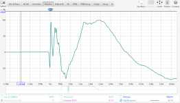
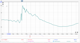

But this is only possible if the filter does not rotate the phase at the crossover frequency.
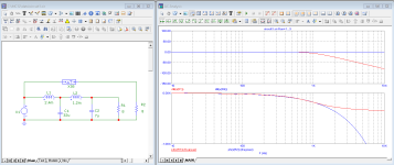
this is a crossover i did for a coax compression driver, on real measurments in the horn. The horn will cross to a woofer with dsp (with eq).

you see the dotted lines, they are the phase (colour corresponds to colour response of band). I aligned both drivers (not physically aligned) with asymetric filters. This crossover is 4th order with 5 components (2 caps, 2 coils and one resistor) and almost perect phase ligned in the crossover band. It's not always that easy, but the principle is the same. Use real measurements with the drivers in the horn or cabinet and use asimulation software that shows phase per driver and in total (here it's XSim, but Virtuixcad can do that also).
you see the dotted lines, they are the phase (colour corresponds to colour response of band). I aligned both drivers (not physically aligned) with asymetric filters. This crossover is 4th order with 5 components (2 caps, 2 coils and one resistor) and almost perect phase ligned in the crossover band. It's not always that easy, but the principle is the same. Use real measurements with the drivers in the horn or cabinet and use asimulation software that shows phase per driver and in total (here it's XSim, but Virtuixcad can do that also).
Delay can be seen to change the slope of phase over frequency, as cycles are accounted for in the time of the delay.introducing a delay into the channel for synchronous operation of the speakers is not a correction of the phase of the speakers, since the delay does not twist the phase of the speaker itself,
Changing phase also demonstrates a delay, as is shown here.. and it's passive 😉
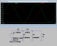
Yes, of course it is.Delay can be seen to change the slope of phase over frequency,
I separated the delay from the phase influence on the signal purely for my own simplification of the processor analysis.
This is strictly speaking not correct, but it is easier for me not to get confused.
A passive filter twists the phase when the frequency changes, i.e. the signal phase changes from 180 degrees to - 180 degrees, and the delay creates the same phase slope on the entire frequency scale. Unlike a passive filter, the delay does not twist the phase, it only sets a constant angle of inclination of the change in this phase from the change in the signal frequency. And actually, if we consider the delay through the signal phase, then this sometimes confuses the cards a little. Of course, in passive filters it will not work to separate the delay from the phase twist, since these two phenomena are interconnected, but in FIR filtering, it is easy to separate the delay from the phase twist, and as a result, if you accept in your head that the delay does not twist the phase, then the analysis of the processes is simplified.
In my understanding, twist the phase is when the phase is not a straight line on the frequency scale.
I do not insist that this is a recognized terminology and it should be used, I am just explaining my approach to analysis, an approach that is not correct, but sometimes it greatly simplifies for me the analysis of processes in an active three-way speaker system.
Once the delay accounts for what it is there to account for, the phase will rotate just the same.Unlike a passive filter, the delay does not twist the phase,
It is not a bad thing, it is just delay. It's not the same as phase not being flat with a flat response.twist the phase is when the phase is not a straight line on the frequency scale.
Try looking at a measurement in REW and change the delay. The phase will rotate but it means nothing as it contributes flat group delay.
If I understand you correctly, you are talking about a logarithmic scale along the frequency axis, a scale on which the delay is not a straight line, you just need to switch to a linear frequency scale to see the straight line I am talking about.Once the delay accounts for what it is there to account for, the phase will rotate just the same.
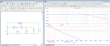
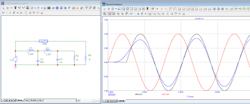
Did you mean to compare the low pass filter to a pure delay?
Nothing so complicated. Simply that when you implement a crossover, and exchange some or all of the available phase shift for plain delay, the resultant crossover phase will be the same..If I understand you correctly, you are talking about a logarithmic scale along the frequency axis,
Last edited:
I'm just explaining why I don't call the delay a phase twist, the delay doesn't twist the phase. It's just easier for me, that's all.Nothing so complicated. Simply that when you implement a crossover, and exchange some or all of the available phase shift for plain delay, the resultant phase will be the same.. it has to be or it wouldn't work in a crossover, would it?
If the crossover filter doesn't twist the phase, then summing two bands is quite easy without resorting to complex formulas. A simple delay will pull out the acoustic centers and that's it, but if the filter twists the phase, then summing two bands is complicated by the different phase in each band, and a simple delay won't help this matter much. In addition to all this, the very principle of the IIR filter makes it impossible to eliminate the transient process, and when summing the bands, the transient process is not eliminated, unlike the FIR filter. Simply put, the IIR filter introduces linear distortions into the final result that cannot be eliminated, but that's a slightly different swamp that I don't really want to delve into...
I'm just explaining why I don't call the delay a phase twist, the delay doesn't twist the phase. It's just easier for me, that's all.
It's not only easier....it's 100% correct. 😀
Let say delaying the tweeter pulses and keeping their phase unchanged at the same time is nothing more than moving the physical tweeter backwards, if that's what urii-ch is trying to explain? Yes, it's a very good way to phase align say bass and tweeter, dsp delaying or physicaly moving nevermind. And not only that, it is possible to make a first-order filter in the same time! Only first-order filters have linear phase, and when you're lucky enough to get two speakers, say a bass and a tweeter with very similar sensitivities, both of which also have a very linear response characteristic, and first-order gives perfect phase alignment, than that speaker could be holy grail speaker , for example something like this https://www.humblehomemadehifi.com/download/Humble Homemade Hifi_Plutone.pdf , In no doubt I assume it sounds brutally correct, especially because of the choice of speakers, a well made HMQ driver by Troles Gravesen, a very eficient driver , and that beryllium tweeter, at the same time perfectly matched and very well and carefully designed with a first order crossover, must sound very good! I'm not advertising, just guessing!
Last edited:
I have to write a few more lines , I received here more than I expected, you are great, all my respect and thank you all.
Interesting discussions, you know a lot about speakers,many good tips for me,correct conclusions.
Because it's possible to buy cheap boxes weaker than mine ,I'm not giving up ...yet.
Like others I prefer full range sometimes ,VTP or DDVP20, for sound and simplicity more suited to my abilities ,with a tw is better.
I need time to study what you say here, GM doc, those links.
All my best wishes ,If possible, I will come back with other questions.
The property you are describing here is excess group delay, and in a typical crossover there shouldn't be enough of it to be audible.. even with waveguided speakers that have larger offsets.the very principle of the IIR filter makes it impossible to eliminate the transient process, and when summing the bands, the transient process is not eliminated,
DSP happens to be easy to misuse though, and this can lead to stories of problems that shouldn't happen. Very steep filters are not normally needed and their use can lead to too much group delay.
None of this should matter though because the best place to apply FIR when it's necessary may be outside the crossover in a single pass. Not only is this simpler, but it avoids accidentally covering up un-equalisable acoustic problems that are supposed to be treated physically. If for some reason you are using FIR because you are having difficulty, then it may be more of a shotgun approach.
I think too many things are being mixed together to try to make sense of any one of them....
The one factor that should be sorted out first, before beginning with all that follow.....is that of fixed delay vs frequency dependent delay.
Unfortunately, both of those types of delays are included in the mathematical definition of group-delay, so we seldom know exactly what type delay someone is discussing when they say 'group delay'.
(curse the mathematicians and signal processing folks, or whoever originally included constant delay into audio bandwidth group-delay discussions lol)
It's a huge problem hindering both discussion and understanding ..... because fixed delay and frequency dependent delay are not truly interchangeable.
Which basically means time and phase are not substitutes for each other.
Further compounding misunderstanding, is the idea that the group-delay curves of electrical xovers contain a fixed time component.
That component being the difference between the flat GD regions on either side of the xover.
For example: in the 300Hz LR24 xover below, its group-delay curve is in blue.
(GD curve is same for all..... the red high-pass side, green low-pass side, and black sum)
GD = 0ms at higher frequency, and about 1.5ms at low frequency.
I've seen more than one post saying that the 1.5ms of GD difference between high and low like in this example, can be used as a fixed time substitute.
It cannot. It is not real fixed time. The GD curve just a particular mathematical depiction of phase rotation.

Bottom line: time (constant) and phase are NOT substitutable equivalents.
They can be made to show a relationship with each other using frequency, but that does not mean they can be used as substitutes, unless we are talking for one specific frequency only
Once that got beat into my mellon, I could move on to more easily understand other things.....like IIR vs FIR... min-phase vs lin phase, group-delay vs excess GD, etc etc
Until the realization that fixed time and phase are different animals and not substitutes clearly sinks in.....we chase our tails endlessly it seems..
The one factor that should be sorted out first, before beginning with all that follow.....is that of fixed delay vs frequency dependent delay.
Unfortunately, both of those types of delays are included in the mathematical definition of group-delay, so we seldom know exactly what type delay someone is discussing when they say 'group delay'.
(curse the mathematicians and signal processing folks, or whoever originally included constant delay into audio bandwidth group-delay discussions lol)
It's a huge problem hindering both discussion and understanding ..... because fixed delay and frequency dependent delay are not truly interchangeable.
Which basically means time and phase are not substitutes for each other.
Further compounding misunderstanding, is the idea that the group-delay curves of electrical xovers contain a fixed time component.
That component being the difference between the flat GD regions on either side of the xover.
For example: in the 300Hz LR24 xover below, its group-delay curve is in blue.
(GD curve is same for all..... the red high-pass side, green low-pass side, and black sum)
GD = 0ms at higher frequency, and about 1.5ms at low frequency.
I've seen more than one post saying that the 1.5ms of GD difference between high and low like in this example, can be used as a fixed time substitute.
It cannot. It is not real fixed time. The GD curve just a particular mathematical depiction of phase rotation.
Bottom line: time (constant) and phase are NOT substitutable equivalents.
They can be made to show a relationship with each other using frequency, but that does not mean they can be used as substitutes, unless we are talking for one specific frequency only
Once that got beat into my mellon, I could move on to more easily understand other things.....like IIR vs FIR... min-phase vs lin phase, group-delay vs excess GD, etc etc
Until the realization that fixed time and phase are different animals and not substitutes clearly sinks in.....we chase our tails endlessly it seems..
A small victory for me...I think.
In xsim the phase display implies that it must be created by checking
- speaker
-FRD phase source-derived (not as measured )
-ZMA phase source-derived (not as measured )
Otherwise the phase is missing or is a straight line.
This is because my frd, zma files were obtained with FPGraphTracer from images(PDF speakers) with SPL and impedance graphs.
It is true?
The phase is created with some math?
How do you get frd,zma with phase ?
Does REW software directly generate frd and zma that also contain phase data?
(without the need for FPGraphTracer)
No, this isn't true. The real phase of the speaker (the one that matters) is optained by measuring the driver in the cabinet, and all drivers from the same point measured at the sam output volume. Those measurments are the only ones that wil give you the right info about how your drivers react in that box (what matters), so you can make the right filters for it (be it passive, active analog or dsp).
Derived measurements are for me very handy for prestudies of speakers, to see if i can match the drivers right in the setup that i have in mind, but they are generalised and smoothed, so they only give a rough id on what is possible, a crossover based on those will not be finetuned, it will be a very rough filter and very often not sound good at all (you can be lucky, but it's luck, not engineering).
Derived measurements are for me very handy for prestudies of speakers, to see if i can match the drivers right in the setup that i have in mind, but they are generalised and smoothed, so they only give a rough id on what is possible, a crossover based on those will not be finetuned, it will be a very rough filter and very often not sound good at all (you can be lucky, but it's luck, not engineering).
Previously we have established this, real data through measurements, no doubt.
I don't waste any more money on a new filter until it's done right.
For measurements, I can't buy the necessary ones now.
The heating is being replaced in my apartment, a lot of trouble and expense.
It's not my plan to do this when it's very cold outside, that's how it's programmed by others.
So now I can only simulate, learn to do this better ,look for information about how the measurements are made
And use the speakers as they are.
That's why I would appreciate the answers.
- Home
- Loudspeakers
- Multi-Way
- 3 way my version