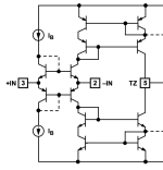
The pTA consists of a connected pair of OTA's to simplify balanced input/output functions, wanting to avoid the matching of numbers of precision resistors without resorting to INA's necessarily. It takes advantage of the formidable current mirroring (shown below on the right) and the CMRR already existing in AD844 devices, adding a linearization input network using an NE5532 dual VFA op-amp. Although this pTA cannot match the minimalist distortions or CMRR capabilities of the best INA's it does an excellent job IMO without using global feedback, producing a pair of differential phase aligned output currents.
The pTA supports differential input signalling, allowing for a broad range of applications left to the imagination of anyone here to use. The NE5532 input device bypasses the non-linear transconductance of the input buffers in each of the AD844 CFA's. In so doing the pTA has much lower distortion and can generate programmable currents using a single resistor, in this case R6, in a simple calculation using Ohm's law in relation to the differential input voltage.
As this current is channeled to flow only into (or out of) the inverting terminals of opposing AD844's, the currents are equal in feeding into their respective current mirrors, being also complementary matched in the folding over with AC, a condition that generates equal amplitude differential currents phase aligned over wide frequencies. Phase alignment is of advantage in the process of converting back from differentials to single ended at the receiving end.
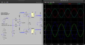
A basic implementation of the pTA is shown in the LTSpice screenshot below. The voltage outputs shown on the right are labelled on top, this corresponds to nodes identified on the schematic, being also colour coded to the waveforms below the labels.


In this simple example a 1 kHz 2 Volt pk/pk signal is presented from a floating source B2 that looks into a 50 kOhm load, being arbitrarily offset by 4 volts DC. The ends feed into U3 and U4 via lines N001 and N006. These appear as red and grey waveforms centered around +4 V DC. The two output signals in yellow and blue are centered around zero volts, being produced by U1 and U2 on nodes N004 and N008 respectively. The output signal voltages can easily be calculated with reference to the input Vin differential signal whereupon for the yellow sine trace has Vo = Vin(diff) x (R11/R6) or 3/4 Vin and the bottom Vo = Vin(diff) x (R2/R6) or Vo= Vin. As can be seen on the schematic the extent the 4 Volt DC is stripped from the output signal is down to 4 or 5 milliVolts, this is close to about -60dB CMRR. To obtain similar results from a resistor based network seems would require resistor tolerances in the order of 0.1%.
I would like to thank Hans Polak for his assistance in reviewing this material, for conducting simulation experiments on distortion and for assisting in the learning and using of LTSpice. I hope that the material presented is of use to anyone wanting to experiment with it... and hope that the results are shared...forget it if its negative though...quiet...no I won't!...I'm warning you...make my day punk!...stop it... people with start to think I'm crazy... I know I do...
The pTA supports differential input signalling, allowing for a broad range of applications left to the imagination of anyone here to use. The NE5532 input device bypasses the non-linear transconductance of the input buffers in each of the AD844 CFA's. In so doing the pTA has much lower distortion and can generate programmable currents using a single resistor, in this case R6, in a simple calculation using Ohm's law in relation to the differential input voltage.
As this current is channeled to flow only into (or out of) the inverting terminals of opposing AD844's, the currents are equal in feeding into their respective current mirrors, being also complementary matched in the folding over with AC, a condition that generates equal amplitude differential currents phase aligned over wide frequencies. Phase alignment is of advantage in the process of converting back from differentials to single ended at the receiving end.
A basic implementation of the pTA is shown in the LTSpice screenshot below. The voltage outputs shown on the right are labelled on top, this corresponds to nodes identified on the schematic, being also colour coded to the waveforms below the labels.


In this simple example a 1 kHz 2 Volt pk/pk signal is presented from a floating source B2 that looks into a 50 kOhm load, being arbitrarily offset by 4 volts DC. The ends feed into U3 and U4 via lines N001 and N006. These appear as red and grey waveforms centered around +4 V DC. The two output signals in yellow and blue are centered around zero volts, being produced by U1 and U2 on nodes N004 and N008 respectively. The output signal voltages can easily be calculated with reference to the input Vin differential signal whereupon for the yellow sine trace has Vo = Vin(diff) x (R11/R6) or 3/4 Vin and the bottom Vo = Vin(diff) x (R2/R6) or Vo= Vin. As can be seen on the schematic the extent the 4 Volt DC is stripped from the output signal is down to 4 or 5 milliVolts, this is close to about -60dB CMRR. To obtain similar results from a resistor based network seems would require resistor tolerances in the order of 0.1%.
I would like to thank Hans Polak for his assistance in reviewing this material, for conducting simulation experiments on distortion and for assisting in the learning and using of LTSpice. I hope that the material presented is of use to anyone wanting to experiment with it... and hope that the results are shared...forget it if its negative though...quiet...no I won't!...I'm warning you...make my day punk!...stop it... people with start to think I'm crazy... I know I do...
They appear red & cyan to me...These appear as red and grey waveforms
They appear green & blue to me...The two output signals in yellow and blue
The blue sine appears 25% larger then... the other one.
How does the nodes 1/2/99/50/28/12 on the left correspond with the nodes 3/2/5 on the right?
It's obvious for the inputs and the output, but has an AD844 up to 99 pins?
I'm sure my eyesight is degrading, so your final words in such a small font proove impossible to read, if it matters at all.
You need to be colorblind to see the colors as I do...
The blue sine is actually closer to 33% larger than the yellow (... 33% larger than the green if your eyesight is so pre-inclined...)
By law AD844 packages manufactured in Canada must contain numbers of pins equal to that of Wayne Gretzky's jersey number...
The little man in my head can't reach the larger fonts...and I never know what he is thinking...
By the way, have you met Citizen124033? Nice chap?
Last edited:
His real name was Mars Bravo and he chose to be beheaded by Pano a few years ago over a dispute here.By the way, have you met Citizen124033?