I am in the final stages of building a pair of Monoblock ( LL7903/1:8 to a 46 to a LL1671/30mA to a 300B to LL1664/80mA)
I've got all the PSU dialed in and was reading some of the articles from Ale Moglia of how he switched to the 47 for a bit more gain given his 2v input so wanted to check my gain by the stages.
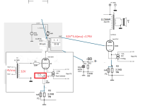
I have a 4V input from the DAC (SMSL su-10) so the 46 would see ~30V on the grid. I almost went to turn the amp on and realized that the Rk on the 46 is at 17.7V. Should this be 32V ish? should I just do a B- supply to this or do a Rk with a higher value to give me the 32 ish V on the cathode?
Obviously the B+ would have to change to around 240@30mA if using the -30 curve.
With the 4V into the LL7903 in 1:8 it yields the 30V and the mu of the 46 is 5.6 which should translate to 168V swing. The max per the LL1671 on the secondary is 130V rms. Will this configuration drive the 300B too hard and the 1671 too hard as well? I have highly efficient speakers at 96db/w/m so I probably wont be cranking it all the way up anyway but wanted to check everyone's thoughts here.
I've got all the PSU dialed in and was reading some of the articles from Ale Moglia of how he switched to the 47 for a bit more gain given his 2v input so wanted to check my gain by the stages.
I have a 4V input from the DAC (SMSL su-10) so the 46 would see ~30V on the grid. I almost went to turn the amp on and realized that the Rk on the 46 is at 17.7V. Should this be 32V ish? should I just do a B- supply to this or do a Rk with a higher value to give me the 32 ish V on the cathode?
Obviously the B+ would have to change to around 240@30mA if using the -30 curve.
With the 4V into the LL7903 in 1:8 it yields the 30V and the mu of the 46 is 5.6 which should translate to 168V swing. The max per the LL1671 on the secondary is 130V rms. Will this configuration drive the 300B too hard and the 1671 too hard as well? I have highly efficient speakers at 96db/w/m so I probably wont be cranking it all the way up anyway but wanted to check everyone's thoughts here.
Attachments
Last edited:
Did you perform a calculation of the input capacitance (including Miller) of the 46?
Then, take into account the square of the turns ratio of the step up input transformer.
Can your DAC drive that load?
Then, take into account the square of the turns ratio of the step up input transformer.
Can your DAC drive that load?
I've built a 2a3 amp where I tried 46, 47 and 10Y as input tubes. The best was the 10Y which clearly had more low level detail and tone. I'd use that. I used a Hammond 1140-LN-C in 1:4 on the input and was pleased with those - Hammond's Studio series. With 4V in you don't need 1:8. Mine worked with just 2V in. I have a pair of those transformers I could sell, though I'm in the UK. Cheaper than Lundahls. I would also use Ogonowski OPTs rather than Lundahl. I'm very pleased with mine. They are better than Lundahls for the same price or cheaper.

@zigzagflux My DAC outputs 4v @ 370ohm, I run long cables and that accounts for 800pF and .2R probably. I have not calculated input capacitance on 46, need to dig deeper into it.
@andyjevans I have a 46 and want to give that a shot first, I built the amp with modular standoff platforms so I can change them around and try other tubes/opt. Will for sure try the 10Y and OPT recommendations!
@andyjevans I have a 46 and want to give that a shot first, I built the amp with modular standoff platforms so I can change them around and try other tubes/opt. Will for sure try the 10Y and OPT recommendations!
IMO the R2//F1 in #46 cathode is completely unnecessary.
If the #46 bias is 17.7V (590R, 30mA), it's A1 limit is at 17.7V peek, 12.51V RMS.
The 1:8 SUT never drive #46 grid over it with problem-free.
The trioded #46 has theoretical gain 5, in practice the maximum (with very large load, like CCS) is 4.7-4.8.
With these parameters max. output about 4.7*17.7Vp= 83.19Vp.
It's may satisfactory, but no headroom for -80V biased output tube.
Are you read Ale's blog, especially this?
-27.5V biased #46 (1:8 SUT, decoupled cathode resistor!!!, 1:1 IT load, 30ma anode current) has overall gain about 40, driving -63.5V biased output tube.
p.s.
#46 capacitance values (from Ale's spice model)
CCG=4P CGP=7P CCP=3P RGI=2000
BTW CCS also unnecessary, if B+ enough quiet (inductor loaded tube has very poor PSRR).
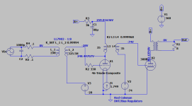
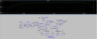
Simulated sample.

As you can see, 1:1 IT loaded old DH tube has relatively large output impedance, so driving capacity at HF, and slew rate problems may occur.
In this case some separation from output tube (practically source or cathode follower) may be necessary.
Simulated sample.
As you can see, 1:1 IT loaded old DH tube has relatively large output impedance, so driving capacity at HF, and slew rate problems may occur.
In this case some separation from output tube (practically source or cathode follower) may be necessary.
euro21 is correct about the need for a cathode bypass capacitor.
Unbypassed cathode resistors cause the anode driving impedance to increase; but we need a good low value for transfomer drive.
Also, above 30Ω or so, unbypassed cathode resistors will increase noise (mains fundamental: 50 or 60Hz), due to common mode leakage from the power transformer.
Unbypassed cathode resistors cause the anode driving impedance to increase; but we need a good low value for transfomer drive.
Also, above 30Ω or so, unbypassed cathode resistors will increase noise (mains fundamental: 50 or 60Hz), due to common mode leakage from the power transformer.
@euro21: The R2//F1 are there to protect the tube if a failure occurs, F1 is 150mA and R2 will force the tube to cut-off and protect the tube and transformer.
I will be trying the Gyrator/Source follower from Ale but wanted to get a baseline with the IT first prior to that.
@Rod: Thanks for the feedback on the Cathode bypass cap. I knew it felt wrong to just up that value, maybe I read something about it years ago and something inside me told me not to and to pose this exact line of questions here. So thank you!!!
quick Q for you. IF I do go the route of B- on the SUT and completely forgo the cathode Rk and Ck could the same single -Raw DC feed the 300B Negative Bias Regulator and the 46 Negative Bias Regulator? like the image attached
Attachments
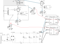
Yes, you can share supplies between bias regulators, so long as they are on the same chassis (if not, there can be ground loops).
The Bias regulator is at Version 5 now - details at the usual web pages.
No need for any parts on the output - connect directly to the transformer secondary.
The Bias regulator is at Version 5 now - details at the usual web pages.
No need for any parts on the output - connect directly to the transformer secondary.
Thanks Rod. Great news, don't have to build another PSU and add another Tx. Yes Same chassis, monoblock build.
No parts as in the C1/R3? I saw Ale using them to create a reference 3k for the secondary. This is not needed as V5 of the Bias Reg has that baked into the circuit?
No parts as in the C1/R3? I saw Ale using them to create a reference 3k for the secondary. This is not needed as V5 of the Bias Reg has that baked into the circuit?
The LL7903 secondary is not really loaded at all, as drawn - since the grid should be nearly open-circuit at low frequencies. If it needs a matching load , connect it directly across the secondary. Some Lundahls need matching loads - depending on the primary drive impedance
The 3k || Cap is not required, because my V5 (and previous) Bias regulators' output is carefully designed to handle the small currents coming in, with low impedance and vey low noise (µV region). Actually, adding caps will degrade it slightly, so it is best to remove any parts from the output, and the sound will be optimized!
The 3k || Cap is not required, because my V5 (and previous) Bias regulators' output is carefully designed to handle the small currents coming in, with low impedance and vey low noise (µV region). Actually, adding caps will degrade it slightly, so it is best to remove any parts from the output, and the sound will be optimized!
Thanks Rod, much appreciated, they are now deleted. I was actually planning on soldering a small little PCB today with those parts so one less step to do!
The triode symbol is the same for 300B as the 46 symbol, if you're using Dmitry Nizhgorodov's library.
If you look inside the model file, the 300B-Composite model should be there. Just use this as the label (R-click the label). I believe that the 300B is the default model for the symbol (when no label is set).
If you look inside the model file, the 300B-Composite model should be there. Just use this as the label (R-click the label). I believe that the 300B is the default model for the symbol (when no label is set).
1:8Anyone have the inductance/series resistance figures for a LL7903
Each primary is 28R, paralleling all, sum 7R;
Each secondary is 125R, series all, sum 500R.
The inductances 5.3125H, 340H.
Coefficient 0.9991.
Snubber on secondary: 30k series 180pF.
The simulated fr. behaviour is poor: -3dB 17Hz...18kHz
ps.
If you use another snubber (Zobel), the HF can be pushed out .. with some falling ..
Last edited:
Thanks @euro21 I had the Rs dial in but not that Lp, yes that Zobel did work, I saw Ale had it in his 46 posts, I tried his values and they dropped the HF above 4k quite a bit.
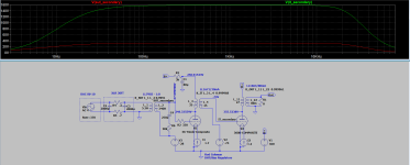
The values you proposed definitely fixed that HF bump, I tried a few values and found 90k and 250pF to work best, resulting response in attachment 1.
I ran and sampled the Voltage on secondary for the SUT and secondary of the IT and as I expected around 30ish V for the SUT and ~160V for the IT(second attachment).
Since I biased at -74 would the 300B get into A2 a bit or since the theoretical gain isn't exactly 5.6 for the 46 but much lower it will stay in A1 at max input?
Attachments
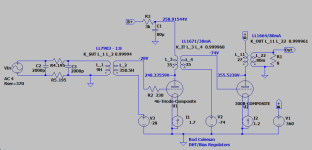
If you have 4V RMS DAC output, why do you use problematic 1:8 connection for SUT?
As you can see, the 1:4 SUT can drive 300B grid up to A1 at 3.57V RMS input.

As you can see, the 1:4 SUT can drive 300B grid up to A1 at 3.57V RMS input.
Using the 1:4 I get 80V on the IT_secondary node, Im new to LTspice the 80V is not the Vp-p is it? just the positive swing? That would mean my 160V in the 1:8 is grossly over.... plus like you say the 1:8 is problematic.. I updated the SUT for 1:4 on Hp/Rp and it looks good. might up the operating point/bias a bit too. Thanks euro21!!!
Friday I set you one zip file via "direct message".
It contains the working 1:4 SUT, #46 , 1:1 IT load asc file.
If you use spice directives from this asc in your schematic and run "Transient" simulation, after the run down, the View-Spice Error Log shows distortion and measured voltage parameters.
These are my usually used directives for amplifier:
.option noopiter
.option plotwinsize=0
.param period=1m, ncycles=100
;tran 0 {ncycles*period} {(ncycles/2)*period} {period/1e4}
.four {1/period} 9 -1 V(Ug)
.four {1/period} 9 -1 V(Out)
.MEAS TRAN Output PP V(Ug) TRIG time=20*period TARG time=40*period
.MEAS TRAN power_Output AVG I(RLoad)*V(Out) TRIG time=20*period TARG time=40*period
The frequency of the input signal is: {1/period}
The "period" -in this case- is 1msec, so frequency is 1kHz.
- Home
- Amplifiers
- Tubes / Valves
- 46 driving a 300B