As I have two LL1667 5mA lying in my box, I thought of giving them a chance in the concertina, for a 15W 6B4G PPP for my 414-8A midbass 60-350Hz. With coils in opposite phase 15mA is max. Would be great if it worked as planned as there will be less problems with max swing compared with a conventinal inverted concertina with the available 270V B+. Will try to find a suitable low Cin MOSFET if the 2540 isn´t good enough. Driver before the concertina is a trioded 6E5P.
Could anyone please do a sanity check of the circuit. Sims good, but you can not see what will happen at higher frequencies. Tried to get capacitance and K figures from Lundahl, but they couldn´t help me.
Could anyone please do a sanity check of the circuit. Sims good, but you can not see what will happen at higher frequencies. Tried to get capacitance and K figures from Lundahl, but they couldn´t help me.
Attachments
Sorry, forgot to sanity check. It does not workas planned😱.
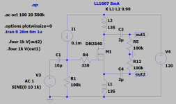
This one works better.

This one works better.
Attachments
Last edited:
Trying the same concept with direct coupled PMOS Concertina, for rebuilding my monoblocks, with no luck, as it starts clipping at ca 15V on one side. Works well below 15V in. 10mA standing current.
Any clues?

Any clues?
Last edited:

Something feels wrong here. Wouldn't this be electrically equivalent to a PP output stage operating with the same signal on both grids...?
I've been wrong before but I think this only works of you either flip one coil or use two separate inductors.
Besides, isn't the 1667 a choke with one coil on each leg of the core and no interleaving? Seems like a non-ideal choice, but the modest bandwidth requirements may save the situation.
I've been wrong before but I think this only works of you either flip one coil or use two separate inductors.
Besides, isn't the 1667 a choke with one coil on each leg of the core and no interleaving? Seems like a non-ideal choice, but the modest bandwidth requirements may save the situation.
This is a tricky one, but it works, no question about that. If you turn one coil so both are same phase, strange things happen(3rd image).The DC current cancels with the posted connection, but so does the AC.
I am not able to explain, but nothing wrong with the sims. It is all about how close K you have. If the coils where tightly coupled, you would get big resonances higher up and worse performance of the one with opposite phase. It´s a pity Lundahl don´t have the figures.
My main issue is still why the PMOS version clips?
Opposite phase:
Same phase:
Last edited:
Have now made a few more sims and with the coils in phase, distortion figures get better with tight coupling K=0.9996. With K=0.99 they get close to the same whatever phase is used.
From the LTSpice@groups.io:
"K=1 is perfect coupling with no leakage inductance. It is unrealistic.
K=0.99 is a very tightly coupled transformer.
k=0.98 is a good transformer."
From the LTSpice@groups.io:
"K=1 is perfect coupling with no leakage inductance. It is unrealistic.
K=0.99 is a very tightly coupled transformer.
k=0.98 is a good transformer."
Last edited:
As I said, Lundahl couldn´t help me with that issue. If I go below down to 0.99, the opposite phase version seems to sim good.
My LL1668 choke (calculated from measured values) has k= 0.999049.Have now made a few more sims and with the coils in phase, distortion figures get better with tight coupling K=0.9996. With K=0.99 they get close to the same whatever phase is used.
From the LTSpice@groups.io:
"K=1 is perfect coupling with no leakage inductance. It is unrealistic.
K=0.99 is a very tightly coupled transformer.
k=0.98 is a good transformer."
Interesting, but it seems a little high for a ct choke with separate bobins on the same core? What is then K for a good LL OPT? In that case opposite phased coils is out of the question.
Good point, but that shouldn’t be a problem with coils in opposite phase. When in phase, saturation is said to be 25mA.
Anyway, iron seems to complicate things a lot. Might be better to add more voltage to B+ and go for resistors?
Anyway, iron seems to complicate things a lot. Might be better to add more voltage to B+ and go for resistors?
It actually seems to do(or kind of). Simmed at a lot higher signal voltage (45V) and it now showed up. Guess which combination ;-) ? So running them in phase at 5mA is the way to go, the better coupling the less hf peak though. Question is if one could go higher as Fu will be 60-70Hz?The simulator doesn't know about core saturation.
With lower coupling factor 0.9 the opposite phase still works, but Belas figures indicates much higher figures.
Last edited:
The same thing still happens with the DC-coupled Pmos concertina even with coils in phase. Ground reference, this time?


Tried that earlier, but unfortunately got to much distortion cancelling using two drivers and 1:1 input transformer.You could also try an LTP with plate chokes, works pretty well.
Try separate N chan. and P chan. Concertinas with resistors. Then use the ground referenced outputs to get opposite phases. Optional Caps. between matched output phases.
- Home
- Amplifiers
- Tubes / Valves
- New take on the iron Concertina