Hello! In my attempt in cloning the SA-9800 phono pre, I've ran into problems quite quickly. I've finished the PCB, and started getting the footprints on, and when it came to transistors it started going south. I already know I can replace 2SK131S with thermally coupled matched pairs of 2SK170, but other transistors don't seem to be any more available, and I don't wanna risk it and order from AliExpress. Are there modern replacements for those given parts? And do these thermistors have to be specific, or any 10K thermistor will do? Thanks in advance
Attachments
Nobody will be able to give you direct comparison types for every single transistor.
I always use this website: https://alltransistors.com/
to find possible candidates.
Then you have to see what is available on the market...
China transistors don't have to be bad. It's just that you should always be careful with power transistors from China!
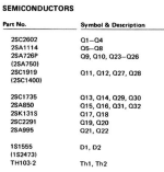
Pioneer has used the TH103-2 thermistor in numerous circuits to compensate for temperature influences. It therefore does not seem to be a specific component that is critical.
I always use this website: https://alltransistors.com/
to find possible candidates.
Then you have to see what is available on the market...
China transistors don't have to be bad. It's just that you should always be careful with power transistors from China!
Pioneer has used the TH103-2 thermistor in numerous circuits to compensate for temperature influences. It therefore does not seem to be a specific component that is critical.
@Pioneer_Exclusive thanks, I tried to use the site, but I'm unsure what to look for when cross-referencing. I'm skeptical about china transistors mainly because prices are really good, like too good to be true territory compared to eBay, is it worth a shot to try? And also I just noticed that there are no resistor values in the SM, they say something about a resistance value code, are the one on parts list written in that code?
Hello Vigothecreator,
it´s quite an ambitious project to clone that phono-preamp...
When choosing replacement types for small-signal transistors, you should make sure that the maximum collector-emitter voltage VCE of the candidate is always greater than or equal to the VCE of the original type. The power is mostly not critical, but it should also be appropriate. It is also better to choose a higher transit frequency fT! The current gain hFE can also be higher. Modern replacement types are usually better in terms of their data than the old originals.
I often use 2SC2229-Y (NPN) and 2SA949-Y (PNP) as standard replacements for NF small-signal transistors in Pioneer amplifiers (P<0.8W). Both have TO-92L housings, which always somehow fit on the circuit boards... I once bought 2 packages of 100 of them each - in China! I measured them and found almost no deviations within the series! These parts work perfectly as replacement types, wherever they have been.
The double transistors are more problematic, however. Simply gluing two single transistors together will not produce the same result. The thermal coupling is then always worse, but it will work somehow...
I assume you also have the service manual, which is widely available as a PDF file, e.g. on hifi-engine. If not, i could send it to you. In the parts list for the phono preamplifier, there are only small squares where the values should be. However, you can find the resistance values in the circuit diagram, e.g. 11.2 "Schematic Diagram" (page 27 top right below "Equalizer ***`y" or you look at page 28, assembly plan for PCB "EQ ***`y GWF-116").
I wish you much success!
Pioneer_Exclusive
@Pioneer_Exclusive thank you for your help! Do you mean that I could use those two units in place of all PNP and NPN transistors on the board? I know about the struggle with double transistors, I guess best I can do is buy a matched pair, connect them with a shrink tube and put them in a thermal cap to help with thermal coupling. I do have a service manual, must have missed the resistor values there, again thank you for help and for recommending some replacements!
Hello Vigothecreator,
it is not certain whether the types I have mentioned will really work perfectly everywhere. Sometimes, in addition to the basic data such as collector current, power, collector-emitter voltage, etc., very specific properties such as noise behavior are also important.
Compare the data of my "universal types" with the originals in detail - you should definitely make the effort. Perhaps you will notice something special somewhere.
Recently I had to replace transistors in an Exclusive C3 phono preamp due to horrible crackling noises. By the way, I found the culprits by heating the individual transistors one by one or cooling them with cold spray. Defective transistors usually report problems immediately when heated...
My "universal types" were the right fit and everything is working perfectly again! 🙂
@Pioneer_Exclusive I am now wondering, what part of the board is the MC section? I don't plan on using MC cartridges, and wanted my clone preamp to be only MM, and I guess cutting off a portion of the board would significantly help with finding proper transistors, as there will be less to look for
I am now wondering, what part of the board is the MC section?
Hello Vigothecreator,
I took a closer look at the circuit diagram. Since switch 2 is shown in the MC position, the signal from the phono 2 input goes to the MC amplifier. This consists of 8 transistors e. g. on the left channel. For the left channel, these are Q1, Q3, Q5, Q7, Q9, Q11, Q13, Q15. On the right, the same applies. The entire circuit around these transistors can therefore be omitted for MM pickups.
The input for MM is at the connection point of resistors R49 and R51 (left channel) or R50 and R52 (right channel). That's how I see it.
MM has a much higher signal level than MC and the input of the RIAA network does not need the upstream preamplifier made up of the 8 transistors mentioned.
With MC, the cartridge load section is not needed. Have you thought about that? MM may need CR. The components for that are located on
--> CR ***`y...
By the way, I didn't even know that the SA-9800 could process MC. The blue series didn't make it into my collection... I don't love the blue light and if the display elements are defective, it's almost impossible to repair.
Why do you want to build a replica of the phono amplifier from the SA-9800? What's so special about it?
Best regards,
Pioneer_Exclusive
@Pioneer_Exclusive i've wanted to make my own preamp based on a vintage amp phono stage, because I heard that amplifiers from this time period had the best phono stages because vinyl records were the main hi-fi audio sources then, and engineers put more effort in designing them, and I read that top of the line pioneers from this line had one of the best phono stages there were, described by some as "CD quality" (which kinda doesn't make sense to me from a technical standpoint, because comparing digital to analog is finicky, but I got the sense that it's describing the accuracy of a phono stage), and when looking at specs, 0.005% THD and RIAA deviation of 0.2% look promising, I think. I don't know if it's the best out there, If you have something that is better I'll gladly take it into consideration as I'm not dead set on one circuit in particular, I'm just going by whatever the internet had told me that represents the top notch quality in turntable preamps
Yes, the phono stage of the SA-9800 is certainly very good. But copying it so well that it comes close to the original is not that easy. I see the main problem in the double transistors, for which there are no real replacement types. The inevitable deviations due to the necessary DIY solutions could significantly reduce the quality of the replica.
You will also need a very good power supply and the wiring must also be perfect if you don't want to have problems with the 50Hz hum.
I think this could be a more extensive project than you suspect.
But OK, that's the challenge of DIY...
I don't have a suggestion for a better RIAA network either, because I don't listen to records very often. But then I do use my Pioneer amplifiers.
Linear integrated has dual Jfet in one package LSK489 also numerous surface mounts from TI and others
2SK170 on dual matched package is I believe LS844
For BJT transistor current mirrors or sources needing matched gain and thermal coupling there is also numerous
dual matched transistors from Toshiba.
You can find through hole devices for Jfet with mentioned linear integrated parts.
Dual matched BJT thermally coupled in same package will be surface mount.
Be rather easy to duplicate older circuits. Everything passive can still be through hole.
Only the BJT matched pairs will be surface mount.
@WhiteDragon that's actually a great suggestion, I never thought about SMD, and that would be pretty easy to modify the board layout for I think, I'll definitely look into that.
@Pioneer_Exclusive you're definitely right about that, but where's the fun without the challenge? For now, I have the whole EQ Assy PCB traced in KiCAD as close as possible to the original to keep the original layout, and now I'm planning to cut off the MC amplifier and rotary selector terminals from the design, leaving me with only the MM section, then I'll have to figure out how to incorporate CR assy into the design, and modifying the traces for SMD dual jFETs like white dragon suggested. I'm planning on using a linear PSU that will be connected to the enclosure with a cable to keep it as far from the circuit as possible, and I'll definitely look at some additional shielding for the board
@Pioneer_Exclusive you're definitely right about that, but where's the fun without the challenge? For now, I have the whole EQ Assy PCB traced in KiCAD as close as possible to the original to keep the original layout, and now I'm planning to cut off the MC amplifier and rotary selector terminals from the design, leaving me with only the MM section, then I'll have to figure out how to incorporate CR assy into the design, and modifying the traces for SMD dual jFETs like white dragon suggested. I'm planning on using a linear PSU that will be connected to the enclosure with a cable to keep it as far from the circuit as possible, and I'll definitely look at some additional shielding for the board
- Home
- Design & Build
- Parts
- Pioneer Transistor equivalents