Dear Audiogods,
first ever post on a forum (despite reading stuff here for years).
I would like to build a stereo hi-fi SE amp, I have salvaged/scavenged Mains and OP transformers and a few 12AT7's
I currently have:
- HT transformer 270-0-270V, 3.15-0-3.15, 0-6.3, 0-5v secondary
-2x OP transformer SE 5k 5w secondary
-2x 12AT7
-will buy 2x EL84
When looking at 12at7-el84 schematics I see HT secondaries of 270-0-270 tube rectified and 260-0-260 solid state rectified.
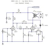
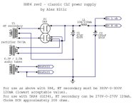
The two circuits below look like an almost identical schematic with slightly different component values, RH84 has a Voltage regulator and a zener the other doesn't.
1)I'd like to understand if putting my 270-0-270 with SS rectification in any of these circuits is ok or will they need adapting?
2)Since I would like solid state rectification, can i simply create a voltage divider with some resistors if I need to drop some excessive voltage?
How come the two circuits operate at almost the same voltage, with almost identical transformers, but Tube/SS rectification?
3)How do I delay the SS rectified B+ from rushing to the tubes before they have the time to warm up?
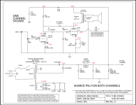
Any advice on which would be the best circuits? One is the RH84 and the other is EL84 SEP by Mike Freda
Attaching schematics
Thanks in advance for any sort of input! Really hoping to make something out of it 🙂
first ever post on a forum (despite reading stuff here for years).
I would like to build a stereo hi-fi SE amp, I have salvaged/scavenged Mains and OP transformers and a few 12AT7's
I currently have:
- HT transformer 270-0-270V, 3.15-0-3.15, 0-6.3, 0-5v secondary
-2x OP transformer SE 5k 5w secondary
-2x 12AT7
-will buy 2x EL84
When looking at 12at7-el84 schematics I see HT secondaries of 270-0-270 tube rectified and 260-0-260 solid state rectified.
The two circuits below look like an almost identical schematic with slightly different component values, RH84 has a Voltage regulator and a zener the other doesn't.
1)I'd like to understand if putting my 270-0-270 with SS rectification in any of these circuits is ok or will they need adapting?
2)Since I would like solid state rectification, can i simply create a voltage divider with some resistors if I need to drop some excessive voltage?
How come the two circuits operate at almost the same voltage, with almost identical transformers, but Tube/SS rectification?
3)How do I delay the SS rectified B+ from rushing to the tubes before they have the time to warm up?
Any advice on which would be the best circuits? One is the RH84 and the other is EL84 SEP by Mike Freda
Attaching schematics
Thanks in advance for any sort of input! Really hoping to make something out of it 🙂
Attachments
Last edited:
Just note there are neither power tubes nor rectifier tubes in your assortment, just small signal tubes and diodes. Your OPT's shout for EL84/6BQ5's, so go and source them.
Best regards!
Best regards!

Edited the initial post in it's entirety as I have conducted further research and have a better idea of what i need and want and hoping I can get help and knowledge from it. I still have some doubts I can't really wrap my head around.
I would not worry about it. When you order the passive components, add an Inrush Current Limiter to the shopping list, like a CL-90, and this will shave some volts off the B+ as well as reduce the kick at start-up.3)How do I delay the SS rectified B+ from rushing to the tubes before they have the time to warm up?
Fit it after the on-off switch before the power transformer, making sure it is clear of other parts and ventilated since it will get hot in operation.
You have a center-tapped PT with the 5v winding, use a 5AR4 tube rectifier. That will fix your #3 and you'll still have plenty of HV.
But that's a myth anyway. Tubes don't conduct HV until they heat up, as soon as they start conducting the HV drops to a safe range. Spend your $$ elsewhere. Do your OTs have center taps on the primary to wire to the screen grids? Ultra Linear operation sounds good and will save you a few parts as well.
RH84 is a good circuit but it has a constant current source connected to the cathodes of the power tubes (the LM317 is not a voltage regulator here) and I would suggest a traditional cathode bias resistor, bypassed, for your first amp. Prob something in the 200-270 ohm, 5w, bypassed by a 220uF/16v cap. Changing the cathode resistors will change the bias voltage, which controls the amount of current flowing thru the tube. Larger value cathode resistors will increase b+, it's good to experiment to find the right value.
Here's an EL84 amp I built earlier this year. PT is only 260-0-260v plenty of power, but I wired the tubes in Triode mode, less output power, easier on the PT.
Last edited:
Thanks a lot @OldHector!
@dubadub the only reason i want to avoid a tube rectifier is to keep the cost of parts down to a minimum. I will also put a resistor instead of a choke. Those alone save me about 60 bucks.
OT's are not center tapped.
Going the cathode bias resistor for sure.
Question: How come you also bypassed the preamp cathode but it isn't in the two schematics provided? Does it make a big difference?
Also, what's the point of having a zener (RH84) on the screen grid compared to a resistor (in yours/the other schematic)?
Sorry if they are very basic questions
One day once I figure this stuff out and manage to build the pentode without blowing myself up, i was thinking of adding a switch so it can be compared to the triode version.
But I need to take all the baby steps first. I've read more forum threads in the last year than books in my life and I still feel clueless..
Ok, nothing wrong there. You'll want a pair of 1N4007 diodes and a pair of 100-330uF 450v caps for the power supply, separated by a 100-330 ohm 5W resistor. I like Nichicon CY series for power supply caps. This page has an amp with a basic power supply,.but you should look at others.
Bypassing of cathode resistors has a great effect on the behavior and sound of a tube circuit. There's probably dissertations on the subject. ValveWizard is a good place to start.
Most power tubes are Pentodes, or Beam Tetrodes that behave like Pentodes, so we call them Pentodes, and they have an electrode called the Screen Grid or g2. The way you provide power to this electrode determines the mode of operation for the tube: if g2 is powered by the main b+ as in this Fender Champ amp, it is a Pentode and producing maximum power. If it is connected to a center tap on the OT, you have Ultra Linear. If you connect the screen grid directly to the plate, the tube is acting as a Triode with lower distortion and lower output. This EL84 datasheet shows the behaviors of an EL84 when operating as a Pentode or Triode in single-ended class A and Push-pull class A and AB.
Ok. So in Pentode mode, the screen grid should be at a lower potential (Voltage) than the plate. The OT drops a few volts, so you need that extra node in the PS for g2, with a dropping resistor to get the g2 voltage a little lower then the plate voltage. The zener diode drops 21v. It's just another method of dropping the voltage of g2.
Switches are cool, you want to explore different sounds and stuff, but switching between Pentode and Triode when the amp is on could break your tweeters. Rare to build a circuit that sounds good in both modes, switch is good to AB test for the final design.
Check out Cascade tubes
Regarding resistors, is it ok to get 1/2W for all the ones that are unmarked? for ex. Audio into G1, Negative feedback, g2 to B+, G2 to ground etc.
Also if I wanted to use a 50k potenciometer (it's what i have lying around) do I simply add a 50k resistor to the grid to compensate for it?
Also if I wanted to use a 50k potenciometer (it's what i have lying around) do I simply add a 50k resistor to the grid to compensate for it?
The impedance at the input interacts with the Miller Capacitance of the tube and can block audio frequencies...stick with the Pot listed in the schematic.
Most resistors in the circuit can be 1/2W metal film but plate resistors get noisy if they are overloaded so I use 1w or better there. In the power supply, wirewound is better, Mox is ok, 5w or better for the CRC resistor, then 1w is ok for screen and driver supply.
Most resistors in the circuit can be 1/2W metal film but plate resistors get noisy if they are overloaded so I use 1w or better there. In the power supply, wirewound is better, Mox is ok, 5w or better for the CRC resistor, then 1w is ok for screen and driver supply.
Ordered all components and will start building asap.
After reading the Valvewizard document I understand the use of the cathode bypass cap. What I don't understand are 2 things:
-Why did you choose 100 and 220uF caps if the graph shows that it is already fully bypassed at 22uF? What's the advantage of using a higher value?
-Since it seems that adding a bypass cap only has advantages(less distortion, preventing cathode feedback, decoupling AC) except for lowering gain. Why don't the two schematics I provided have a bypass cap on the preamp? Is it because 12AT7 already has a pretty low gain?
As I understand it, larger-than-minimum values for K bypass caps are used to overcome low frequency loss at other points in the circuit. But I'm no expert.
As for un- bypassed gain stages, the circuit designer has a variety of reasons to use or omit that cap: perhaps less gain is demanded, to avoid overdriving the power stage. Perhaps a feedback signal is inserted at that point and a bypass cap would cause a phase shift. Perhaps the circuit designer wants the local feedback generated by the lack of a bypass cap.
Of course, fixed bias circuits don't have bypass caps as the cathode is connected directly to ground and there is no need for a bypass, but that tends to be only found in output stages.
No such thing that "fully bypassed".-Why did you choose 100 and 220uF caps if the graph shows that it is already fully bypassed at 22uF?
R bypassed C has frequency dependent impedance.
1k8//22uF (ideal capacitor) has -for example- at 10Hz such impedance which is corresponding to 723 Ohm.
With 100uF it's 159R, with 220uF only 72R.
The 22uF would be the minimum size for 20Hz bandwidth, but a larger size (100uF to 220uF) would reduce phase shift.
It's better for amp LF stability to leave those lower frequencies unbypassed and let the degenerative FB kill the gain on them, if they exist.
Last edited:
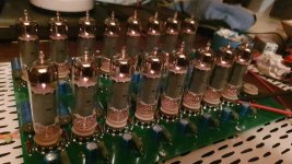
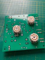
Components arrived, now I'm converting the schematic to a component layout using turret boards. So far this is what I have for one channel. I tried to keep all the ground on one side.
Is there anything to keep into mind when doing such layout?
Any wires worth twisting together apart from heaters?

Is there anything to keep into mind when doing such layout?
Any wires worth twisting together apart from heaters?
Careful what gets close to the Cathodes wire. I've gotten a nasty buzz that way. Went back to point to point on that amp, got quieter. Turret boards are nice in guitar amps where the sockets are on the side of the box.
Coz lead dress is so important. Wires with hundreds of volts running this way and that will induce noise and oscillations where they cross other wires. Sometimes turret boards can make that worse.
Coz lead dress is so important. Wires with hundreds of volts running this way and that will induce noise and oscillations where they cross other wires. Sometimes turret boards can make that worse.
@andyjevans do you mean a pair per side in parallel?
Currently i’m limited to 5W output transformers as I’m trying to keep the cost as low as possible.
Currently i’m limited to 5W output transformers as I’m trying to keep the cost as low as possible.
Why not eight?Have you considered a pair of EL84 in PSE triode? Could you do with a little more power?
Edit, in case you want to build a SE amplifier on a PCB. I have one PCB remaining for EL84SE. its free, you only pay the postage.
Attachments

Last edited:
- Home
- Amplifiers
- Tubes / Valves
- HELP 2nd amp build: Adapting a schematic to the components i already have