I want to build a bass reflex box for this discontinued speaker, I have been looking for information and I think the bass reflex option is the best fit, but I would like someone to guide me through the design process.
I have been using winisd and hornresp, with winisd I understand myself better, but the port it shows is not front, but rear. So I was wondering if the port speed it shows is real or fictitious, as well as the phase interaction between the port and the driver.
I have also made a small design of a 18 mm birch box, it is the typical L shape with some reinforced areas and the 2 square-shaped ports.
The 2 fundamental questions that come to my mind are:
is the port speed real? since too high a speed implies noises. On the other hand, I read that the port must measure at least 1/3 of the diameter of the driver to avoid distortion, I would like to know if it is true.
The interaction between the port and the driver is not too out of phase in the frequency range to be reproduced.
I will leave more information about the project:
driver precision devices 18 br 40
type of music to listen to: hip hop - drum and bass - reggae from 70s in vinyl record to 2023 digital, also funk, soul... mostly outdoors
Greets!
T/S max flat alignment:
Vented net volume (Vb) (L) = 20*308.99*0.32'^3.3 = 143.87
(Ft^3 = (Vb)/~28.31685) = 5.081
Vented box tuning (Fb) (Hz) = 0.42*30.3*0.32'^-0.96 =
F3 (Hz) = 30.3*0.28*Qts'^-1.4 =
(Qts'): (Qts) + any added series resistance (Rs)
Don't know, though trust HR over Winisd, but then quit using it after its Pro program.
It varies based on its displacement (Vd), not area (Sd) and with low Qt drivers the vents usually need to be as much as Av = Sd, which makes it long enough that when I started using box design programs (T/S) I was already pretty well versed on speaker, TL, horn box design, so used its vent part to design a column/tower alignment AKA nowadays may be referred to as a constant or tapered (ML) TL, (ML) TQWT, (ML) horn where minimum size was Av = Sd with low Xmax and what passed for high Xmax back then with up to 4*Vas for the box size to find its Av = Sd.
So in short, design a folded inverse tapered ML-TQWT for best results overall in HR.

I don't have any experience With that type of enclosures... hoW do i start
and Who uses that kind of enclosure in a live shoW?
and Who uses that kind of enclosure in a live shoW?
Here is a VituixCAD simulation of the PD.18BR40 bass driver in an enclosure whose volume is Vb=126 litres, with the vent tuned to Fb=39.0Hz. Three vents are used, with vent length Lv=28.7cm and vent diameter Dv=10cm. The input power used corresponds to 200W re 8ohms. The vent air velocity at this power level seems to be moderate. The low-frequency −3dB cut-off point for this design is a relatively high F3=44.9Hz.

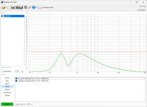
Let us consider increasing the enclosure volume to Vb=150 litres, lowering the vent tuning frequency to Fb=30Hz, and adding a 2nd-order high-pass peaking filter with Fo=29Hz and Q=1.8. With such a design we obtain the following response. The low-frequency −3dB cut-off point for this design is F3=30.0Hz, which is about 15Hz lower than the previous design. Due to the high-pass filter, the driver displacement below the vent tuning frequency is now well controlled.

Let us consider increasing the enclosure volume to Vb=150 litres, lowering the vent tuning frequency to Fb=30Hz, and adding a 2nd-order high-pass peaking filter with Fo=29Hz and Q=1.8. With such a design we obtain the following response. The low-frequency −3dB cut-off point for this design is F3=30.0Hz, which is about 15Hz lower than the previous design. Due to the high-pass filter, the driver displacement below the vent tuning frequency is now well controlled.
Last edited:
Use Hornresp's Design Wizard.I don't have any experience With that type of enclosures... hoW do i start
and Who uses that kind of enclosure in a live shoW?
You didn't mention it was for prosound....... for it (or at least way back when I was involved) Vb = Vas/1.44, Fb = 1.56x Fs yields a 'pounding' mid-bass from the low Xmax drivers of the day, so you might need less speakers using today's high power/Xmax drivers and last time I checked (been awhile), Eminence was still using this for their prime recommended design.
2 questions:Here is a VituixCAD simulation of the PD.18BR40 bass driver in an enclosure whose volume is Vb=126 litres, with the vent tuned to Fb=39.0Hz. Three vents are used, with vent length Lv=28.7cm and vent diameter Dv=10cm. The input power used corresponds to 200W re 8ohms. The vent air velocity at this power level seems to be moderate. The low-frequency −3dB cut-off point for this design is a relatively high F3=44.9Hz.
View attachment 1371878
Let us consider increasing the enclosure volume to Vb=150 litres, lowering the vent tuning frequency to Fb=30Hz, and adding a 2nd-order high-pass peaking filter with Fo=29Hz and Q=1.8. With such a design we obtain the following response. The low-frequency −3dB cut-off point for this design is F3=30.0Hz, which is about 15Hz lower than the previous design. Due to the high-pass filter, the driver displacement below the vent tuning frequency is now well controlled.
View attachment 1371883
about the impedance, both peaks should be at same level, that means the tune is correct?
also, it is dangerous to use it without high pass eq as its going over xmax? if i get noise lower than 30hz it could potentially damage the driver? just curious, i don't have any problem i alredy own a active crossover. got the same info from winisd, also aplied that high pass filter and boom, driver's safe. originally it as 35hz but i could cut lower
Attachments
Yeah, so you recomend me to forget 30hz and 40hz tunning on this one? Hornresp recommend 37.8 hzUse Hornresp's Design Wizard.
You didn't mention it was for prosound....... for it (or at least way back when I was involved) Vb = Vas/1.44, Fb = 1.56x Fs yields a 'pounding' mid-bass from the low Xmax drivers of the day, so you might need less speakers using today's high power/Xmax drivers and last time I checked (been awhile), Eminence was still using this for their prime recommended design.
Last edited:
I contacted precision devices cause i saw a bass reflex design in their web, i could use it and adapt for my speaker?
Box programs default to T/S max flat alignments, which often even optimal in a HIFI/HT app and not the norm for any prosound app I'm aware of and even if wanting lower, it's normally always done with subwoofers out to 80-120 Hz now that electronics have become so (relatively) inexpensive.Yeah, so you recomend me to forget 30hz and 40hz tunning on this one? Hornresp recommend 37.8 hz
No clue, though presume they offer a prosound option or maybe they will do one just for you if calling, etc., is an option same as it was here in the USA way back when with Altec, JBL, etc..I contacted precision devices cause i saw a bass reflex design in their web, i could use it and adapt for my speaker?
In his 1961 paper, Thiele had this to say on the topic:About the impedance, both peaks should be at same level, that means the tune is correct?
"In practice, of course, there are some resistances in the box circuit, which will flatten the peaks at Fl and Fh, and raise the minimum impedance at Fb. But this is incidental, and the relative heights are of little importance. Thus the idea of tuning the box so that
the impedance peaks at Fl and Fh are equal, misses the real point."
There seems to be no intrinsic requirement for the impedance peaks to be the same height for the box tuning to be "correct".
Whether it's "dangerous" or not will of course depend on how loud the system is being driven, as well as the frequency content that it is being asked to reproduce. In the domestic hi-fi marketplace, many small bookshelf loudspeaker systems use vented enclosures. All of these loudspeakers will suffer from significant out-of-band driver cone excursion below the vent tuning frequency if excited by low-frequency content. Most of them seem to survive to play music another day.Also, it is dangerous to use it without high pass eq as its going over Xmax?
Having said that, it is noted that the design specification involves the reproduction of hip hop/drum and bass/reggae/funk/soul music in both digital and vinyl record formats. The latter may be a bit prone to infrasonic signals, say from record warps exciting the tonearm–cartridge resonance frequency (e.g., around 8–10Hz). The chosen music is going to include a lot of low-frequency content that will certainly get to around 30Hz regularly, and no doubt examples with 20Hz content might present from time to time.
If the loudspeaker system will be expected to play at high SPLs, reaching the driver's Xmax limit, then it would be prudent to include at least a 2nd-order high-pass filter (HPF) to help reduce the levels of infrasonic energy that the speakers may be fed.
In any case, it may also be helpful to have the HPF in place if someone decides to play "Disc Wars" by Daft Punk. The frequency analysis shown below indicates the presence of a very strong signal at 18Hz, which is around an octave or so below the typical vent tuning frequencies that might be used. On this track, the use of a HPF would seem to be be a reasonably good idea.
The driver could bottom out and damage itself. I expect that scenario will depend on the driver, and some have non-linear suspension behaviour that helps protect against such occurrences at the extremes of their motion.If I get noise lower than 30Hz it could potentially damage the driver?
I noticed that you used an 8th-order Butterworth high-pass filter. That will attenuate the driver displacement very well. A 2nd-order HPF would probably be adequate.Just curious, I don't have any problem I alredy own a active crossover. Got the same info from winisd, also applied that high pass filter and boom, driver's safe. Originally it as 35Hz but I could cut lower.
So what u think about this, i think i'm on point or i'm totally wrong. Its based on the original PD design, but i calculated my own volume and port tunning based on winisd.
That's 155L 43.5Hz 2 vents 251mm x 72mm (*2) length 21,06
Padding yes or not
Maybe you can give me some advice to improve the design
The enclosure volume of Vb=155litres seems entirely reasonable for the driver. However, the box tuning of Fb=43.5Hz seems to be too high. It will lead to a peak in the low-frequency response at around 60Hz or so, of about 1.5dB. Overall, the low-frequency cut-off will be compromised, which seems to defeat the purpose of having a subwoofer.
A vent tuning of Fb=38.0Hz will produce a much flatter response, which is also a bit more extended. For a standard vented box design, this is likely to perform noticeably better than the Fb=43.5Hz tuning. Under-tuning the enclosure to Fb=33.0Hz will give you a little bit more very low-frequency output below F3.

A vent tuning of Fb=38.0Hz will produce a much flatter response, which is also a bit more extended. For a standard vented box design, this is likely to perform noticeably better than the Fb=43.5Hz tuning. Under-tuning the enclosure to Fb=33.0Hz will give you a little bit more very low-frequency output below F3.
Thank you, i've got some questions cause i didn't understand What u mean on getting about the F3 note, isn't that note higher?
Another question is the max air velocity on the vent. I've read somewhere that speed higher than 20m/s will make undesirable noises. I can fix that by increasing the cross-area of the port. Also i have some limitations cause the design won't allow to use higher vent lenghts than 29cm. If needed, the vents could be redesigned into a longer box, i've seen that in some boxes.
Another question is the max air velocity on the vent. I've read somewhere that speed higher than 20m/s will make undesirable noises. I can fix that by increasing the cross-area of the port. Also i have some limitations cause the design won't allow to use higher vent lenghts than 29cm. If needed, the vents could be redesigned into a longer box, i've seen that in some boxes.
Here in my usage, F3 is shorthand notation for the frequency at which the response is −3dB relative to the passband. It's not the musical note F3, which corresponds to 174.61Hz. Sorry about the confusion.
The maximum vent air velocity does need to be taken into account, and you are correct in saying that increasing the port's cross-sectional area will help to reduce the maximum air velocity. However, increased port area, Ap, requires increased port length, Lv, and oftentimes it can lead to unrealistically long vents. The power level also affects maximum vent air speed, so if you are happy to work at lower SPLs, then the chance of exceeding the maximum vent air velocity recommendations will be reduced.
That's one reason I like to use VituixCAD's enclosure modelling tools, as the vent air velocity is displayed as a function of frequency.
So i've been doing some test and i'm getting diferent result than yours, and these are very close to winisd
I'm running at 700w, i'm not getting higher f3 + problems on xmax and vmax

I'm running at 700w, i'm not getting higher f3 + problems on xmax and vmax
Can you check that you've used the same Thiele–Small parameters? The ones that I used were taken from the Precision Devices website here, and are: Re=5.11ohms, Fs=30Hz, Qms=10.21, Qes=0.33, Qts=0.32.
I note that you are running at 700W. That's a very high power input for this driver. The Xmax problems at low frequencies are a direct result of that high power level. The vent velocity problem is a result of the vent diameter being too small, as well as the excessive power input. Although the PD.18BR40 may have a Power Rating of 700 watts (A.E.S.), that is specified as being "AES Standard (50 to 500 Hz) Program 700 Watts". Note the 50Hz lower limit that is used.
I note that you are running at 700W. That's a very high power input for this driver. The Xmax problems at low frequencies are a direct result of that high power level. The vent velocity problem is a result of the vent diameter being too small, as well as the excessive power input. Although the PD.18BR40 may have a Power Rating of 700 watts (A.E.S.), that is specified as being "AES Standard (50 to 500 Hz) Program 700 Watts". Note the 50Hz lower limit that is used.
Last edited:
Ok so I found the culprit, seems that you where using 8 ohm instead 5.11 which is the Re of the driver.Here in my usage, F3 is shorthand notation for the frequency at which the response is −3dB relative to the passband. It's not the musical note F3, which corresponds to 174.61Hz. Sorry about the confusion.
The maximum vent air velocity does need to be taken into account, and you are correct in saying that increasing the port's cross-sectional area will help to reduce the maximum air velocity. However, increased port area, Ap, requires increased port length, Lv, and oftentimes it can lead to unrealistically long vents. The power level also affects maximum vent air speed, so if you are happy to work at lower SPLs, then the chance of exceeding the maximum vent air velocity recommendations will be reduced.
That's one reason I like to use VituixCAD's enclosure modelling tools, as the vent air velocity is displayed as a function of frequency.
- Home
- Loudspeakers
- Subwoofers
- Need help bass reflex PD18 BR 40