Even the IR LED hisses more than a metal film resistor, and everything that 1st valve/tube does is amplified throughout the system...Correct me if I am wrong, but IR emitters are not particularly noisy.
I am generally using vishay dale 1/4 watt resistors which are actually made in the USA and mil spec. They cost pennies apiece and are not noisy at all.
But maybe it won't be noticeable. See how the IR LED's work out first.
I am about to do another board spin, which accounts for all your suggested additional circuitry and changes, which I appreciate.
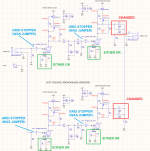
Anything else before I pull the trigger? My schematic is attached.
As an FYI, I use JLC PCB for my prototype board house. They are dirt chip for 2-sided (even multiple layer) gold plated boards, at least in the states. I don't know about Europe or elsewhere though.
https://jlcpcb.com/
Anything else before I pull the trigger? My schematic is attached.
As an FYI, I use JLC PCB for my prototype board house. They are dirt chip for 2-sided (even multiple layer) gold plated boards, at least in the states. I don't know about Europe or elsewhere though.
https://jlcpcb.com/
Attachments
My opinions on two things that I can't agree with, but I find expressed often in Tubes/Valves:
Oscillations in a single stage are never in the audio requency range. They will (must! - just look at the LC values) occur at very, very high frequencies. They are also, maybe mostly, sensitive to signal level, and likely to occur only on parts of a waveform. Stuff happening in bursts at tens or hundreds of megaHertz can be audible, but not as a background noise or tone. Grid stops are insurance against variations with time, changes in valves, loading, EMI/RF interference, etc.
LEDs pretty much cannot be bypassed effectively. Their dynamic impedances when operated at a few milliAmps is only a couple of Ohms, so bypassing them at audio frequenies would require thousands or tens of thousands of uFarads. Something like coupling to a 4 or 8 Ohm speaker. But they're very quiet, so it's not really an issue even for a MM phono stage. Research the numbers and you'll be reassured.
All good fortune,
Chris
If the previously measured values were correct (1.1-1.2V bias, 20.5mA anode current), the 100R resistor and this LEDs aren't interchangeable.Anything else before I pull the trigger? My schematic is attached.
1.1V/0.0205A= 53.7R
1.2V/0.0205A= 58.5R
Practically 57R is good compromise.
My bad. I chose the values based off what LTSpice reported, vs. the actual measurements.If the previously measured values were correct (1.1-1.2V bias, 20.5mA anode current), the 100R resistor and this LEDs aren't interchangeable.
LTSpice reports the anode current draw to be 13mA. In the real world it is 20.5mA, so yes, the cathode resistor needs to be around 50 ohms.