Hello !
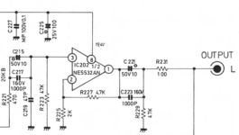
I'm replacing the opamps on a Rotel RC-850 phono stage. The replacements (LME49710NA) have a lower maxium voltage spec, 36V rail-to-rail vs the 44V of the preamp's stock NE5534 and NE5532. The power supply output is +/- 19.4V. It is a simple bipolar PS using a 20V zener reference and voltage follower (schematic below).

I plan to just swap the 20V zeners (D908/D909) with 16V ones. This will be perfect for the phono opamps but the line output and headphone op amps will now see +/- 15.4V and +/- 10.1V respectively. The latter is a bit low but I can probably adjust it by reducing the voltage divider top resistor R908 feeding the voltage follower supply to the headphone amp. For reference the relevant schematics sections are attached.

What are the effects of reducing an opamp's operating voltage in general? I'm guessing less headroom would have an effect on signal to noise ratio, but I believe +/-15V is sufficient for a line amp, as it is a supply voltage often seen for opamps?
That being said, the NE5532s might get the upgrade treatment as well at some point, so I will choose parts suitable for the lower voltage rails then. For the moment I'm only concerned with the phono stage performance as I only use it, directly through the tape loop output.
I'm replacing the opamps on a Rotel RC-850 phono stage. The replacements (LME49710NA) have a lower maxium voltage spec, 36V rail-to-rail vs the 44V of the preamp's stock NE5534 and NE5532. The power supply output is +/- 19.4V. It is a simple bipolar PS using a 20V zener reference and voltage follower (schematic below).
I plan to just swap the 20V zeners (D908/D909) with 16V ones. This will be perfect for the phono opamps but the line output and headphone op amps will now see +/- 15.4V and +/- 10.1V respectively. The latter is a bit low but I can probably adjust it by reducing the voltage divider top resistor R908 feeding the voltage follower supply to the headphone amp. For reference the relevant schematics sections are attached.
What are the effects of reducing an opamp's operating voltage in general? I'm guessing less headroom would have an effect on signal to noise ratio, but I believe +/-15V is sufficient for a line amp, as it is a supply voltage often seen for opamps?
That being said, the NE5532s might get the upgrade treatment as well at some point, so I will choose parts suitable for the lower voltage rails then. For the moment I'm only concerned with the phono stage performance as I only use it, directly through the tape loop output.
Attachments
You might want to consider swapping in OPA1656 in all your locations after the PS reduction. It's hefty output current and rail-to-rail output swing will recover (more or less) all your lost swing due to the lower PS voltage. If you do use the '56 in the headphone amp section, reduce R310 to like 50 Ohms or so. This will make the HP out more compatible with modern headphones. The OPA2156 is a R-R input version of the 1656 and this might be useful in circuits that might have high common mode voltages. I've used the 2156 in circuits where the high side input v range of the TLO72 had been utilized, for example.
You might also consider just using LME49860 which is a 44V part and skip the voltage rearrangement.
You might also consider just using LME49860 which is a 44V part and skip the voltage rearrangement.
I don't mind rearranging the voltage on this preamp, it will be interesting to see if there's any difference in sound after. I'll probably upgrade its line out opamps with some LM4562 left overs from another project as they're rated at 36V R-R too.
However the next upgrade project will be a Rotel RA-930AX integrated amp and I will not try to change its voltage. So I'll check out the OPA1656 or OPA2156 for that, thank you for your suggestions.
However the next upgrade project will be a Rotel RA-930AX integrated amp and I will not try to change its voltage. So I'll check out the OPA1656 or OPA2156 for that, thank you for your suggestions.
Last edited:
This is not an answer to the question, but for moving magnet, the noise current of LME49710 is rather high. For moving coil, it doesn't matter.
What do you intend to gain with this mod? You will reduce your clipping threshold and your system noise floor won't change, reducing the dynamic range of your playback system. Why?

This is a lower-tier preamp and the sound is rather bland. I believe it has potential though, they used Nichicon Muse and polystyrene caps in there and it makes for a nice experimentation playground.What do you intend to gain with this mod?
I'm hoping a "hi-fi" op-amp will have better performance - higher slew rate, lower Zout and all that jazz... But at the end of the day I'm just trying things and enjoying the process.
Hello Marcel,the noise current of LME49710 is rather high
Do you believe it will be audible? This is currently my MM LP setup preamp.
The noise floor will increase, actually.What do you intend to gain with this mod? You will reduce your clipping threshold and your system noise floor won't change, reducing the dynamic range of your playback system. Why?
Hello Marcel,
Do you believe it will be audible? This is currently my MM LP setup preamp.
I don't know. I have seen a thread here where someone who was unaware of the importance of noise current complained about the annoyingly sharp hiss of an MM amplifier with an LT1028, and another thread where someone who used to organize controlled listening test for a living made a similar comment, but an LT1028 has twice the noise current of an LME49710.
(That's assuming the 1.6 pA/√Hz for the LME49710 also holds when the impedances driving the positive and negative inputs are different - which should be the case, as there is no note to the contrary in the datasheet. The LT1028 datasheet specifies 1 pA/√Hz when the impedances driving the inputs are equal, which they normally aren't; under more realistic conditions, it is about 3.4 pA/√Hz. For comparison, it's 0.4 pA/√Hz for an NE5534A.)
Stylus up, I would agree, stylus in the groove, nope, the noise on the disk will dominate. At least this is my experience.The noise floor will increase, actually.
I have no experience with it myself, as I never made an MM amplifier with a large input noise current, but people who complain about the effect of the equivalent input noise current even with stylus in the groove usually complain about the sharp sound of the noise, rather than the level. That sharp sound is due to the cartridge impedance increasing with frequency.
My only decent MM preamp used a 5534AN in the front end and was significantly quieter than when the stylus was in the groove. It would have to be at least 10dB noisier, I would guess, to approach the noise level in the quietest groove. I've read the real world dynamic range of most vinyl is between about 50 and 60dB. This seems resonable to me.
As of a couple of months ago I got rid of my last records. I haven't been able to play them for over a decade.
To the OP I'd suggest stick with the 5534AN, it's about the best you can do in that circuit and is not a bottleneck in your system. Make sure you have a decent cartridge and the loading is correct and be done with it.
That is not a very rational approach.. they could have put those in just for looks.I believe it has potential though, they used Nichicon Muse and polystyrene caps in there
Sounds like a mistake - LME49710 has much higher noise for a MM preamp due to the large current noise spec (1.6pA/√Hz).I'm replacing the opamps on a Rotel RC-850 phono stage. The replacements (LME49710NA) have a lower maxium voltage spec, 36V rail-to-rail vs the 44V of the preamp's stock NE5534 and NE5532
I presume the actual MM preamp opamps are NE5534A's not NE5534's since the A-suffix are the guaranteed low noise devices (screened at manufacture for voltage noise) - nobody normally bothers with the non-A version of the NE5534 as its noisier and you might as well use 1/2 an NE5532 instead with cost-savings.
Because of the very high source impedance of typical MM cartridges (upto 1 henry of inductance commonly) current-noise is usually the limiting factor, not voltage noise - this suggests using JFET opamp, or very low current noise bipolar's (NE5534A are the prime example with 0.4pA/√Hz, 12dB quieter than LME49710NA, assuming the device is 'typical' as max current noise specs aren't given for either chip).
The LME49710NA has a supply range upto 38V, not 36V BTW.
The actual part in the circuit is the Signetics NE5534AN, so if I understand correctly it is guaranteed low noise. I'm cancelling the project since the consensus is that this mod would only worsen performance. Thanks for talking me out of it, I would have lost both my time and system performance...
I'm surprised that a modern opamp, moreover specifically intented for hi-fi applications, has a worse noise performance than a part that came out in 1979. Shouldn't technology improvements bring better performance on all parameters? Noise densities are certainly an important consideration in hi-fi applications.
I'm confused...
When you make an amplifier with a bipolar input stage and you want a very low equivalent input noise voltage, you have to use transistors with a low base resistance and bias them at a relatively large collector current.
When you want a low equivalent input noise current, you have to keep the base current low.
For a given hFE, you cannot increase the collector current without also increasing the base current. There is therefore an optimum collector current at which the total effect of the equivalent input noise voltage and current is at its lowest.
This optimum depends on the source impedance and on hFE. When you use op-amps, you need to pick one that is optimized for roughly the source impedance that you are going to use.
The NE5534A is optimized for impedances of the order of the RIAA- and A-weighted average impedance of a typical moving-magnet cartridge, while the LME49710 is optimized for much lower source impedances. OPA210 or some of the modern FET op-amps would be more suitable for moving magnet.
Thank you Marcel for this very informative reply. I'm guessing that many opamp rollers get caught by installing improperly matched parts.
This optimum depends on the source impedance and on hFE
Is the composition of the source impedance also a factor, e.g. a phono cartridge being mostly inductive one would prefer a lower noise current at the input and another source more resistive or capacitive (interstage coupling) should be matched against a lower noise voltage ?
Or it doesn't matter and one should pick the input operating conditions with the lowest noise figure possible in general without consideration for the noise composition and source impedance composition? If that makes any sense...
Last edited:
That's a very good question that I can only partly answer.
Suppose you were only interested in the noise in a narrow band around one frequency, for example only from 950 Hz to 1050 Hz. It would then (essentially) only be the magnitude of the source impedance in that narrow band that mattered when you wanted to find the optimal combination of equivalent input noise current and input noise voltage. If, for example, the impedance is 3 kohm around 1 kHz, every pA/√Hz has as much effect as 3 nV/√Hz, no matter whether the source is resistive, inductive or capacitive. (The thermal noise that the source itself generates does differ, but not the optimal amplifier input stage and biasing.)
This is, of course, oversimplified, because in audio, one usually cares about the noise over the complete audio band with some weighting or other. Calculating the optimum then gets more complicated because you have to account for both the weighting and the frequency-dependence of the source impedance, but in the end, it is still a kind of averaged magnitude of the impedance that matters. I wrote an article about how to calculate this for a moving-magnet amplifier in 2003, see "Noise and moving-magnet cartridges", Electronics World October 2003, pages 38...43, https://worldradiohistory.com/UK/Wireless-World/00s/Electronics-World-2003-10-S-OCR.pdf There are two errors in this article: Electronics World drew one of the sections of the gain switch in the wrong state in figure 5 and I mixed up the terms spectral density and power spectral density.
Much later, on this forum, both @Nick Sukhov and @kgrlee told me that the spectral distribution of the noise is actually more important than the RIAA- and A- or RIAA- and ITU-R 468-weighted total, because in their experience, sharp noise sounds more annoying than noise that mostly consists of low frequencies, even when it is subjectively about equally strong. (If I understood it correctly, in kgrlee's case, that experience is based on double-blind tests done for a living.)
Assuming they are right, which they probably are, what you wrote in post #18 is also right. For inductive sources, you can then best reduce the noise current a bit further than you theoretically should to get the softest integrated weighted noise. Then again, record surface noise tends to dominate by a large margin unless the noise current is far above the theoretical optimum.
Who does that, a sonar officer in a submarine? loldouble-blind tests done for a living
Very interesting reply. The concept slowly sinks in my brain and I now understand the point you made about my phono preamp input stage current in this post. You referenced your article as well in that thread. I'm sorry I hadn't come around to read it completely - my brain goes into overload when I try, it is very thorough. But I will eventually finish it and hopefully understand it.
I'll also be finishing the phono preamp in question in the next few days. I did try to follow your recommendation but ended up with about 470uA per input transistor with the collector loads value from my simulation so about half the original design but still too high for optimum MM performance. I may tweak these loads to get closer to your recommendation for the next boards, the first board I build usually serves to test the pcb compliance to the design and not a final build.
Last week I tested that single channel board both in MM and MC and it seems it will sound very good. It is actually quieter than the amplifier's phono stage it was cloned from 😎 I can't thank you enough for you help - You are part of that success.
Last edited:
- Home
- Design & Build
- Electronic Design
- Effects of lower op-amp operating voltage in line preamplifier