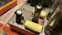
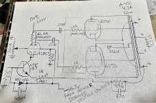
Hi all. Picked up a pair of Dynaco Mk3 for refurb. Didn't pay too much attention to the driver boards. I have seen so many of them over the years, that I can't keep track (stock circuit, 1 tube). Well... I hadn't seen this one. I drew it up to share (neg bias deleted for space). I figure they are individual made, someone's great idea🙄. But the implementation of a ccs, both amps having matching boards, and the cathode feedback with grounding through the secondary...Has anyone else ever seen this particular topology being used for a Mkiii, or anything else? I feel like I always see drivers after the ltp, if and when it is the first stage, and that the cathode feedback scheme looks shady as well...🤷🏼♂️
Attachments
Last edited:
Looks positively dangerous to my trained eye. Mixing HT DC through a valve that may fail Anode to Cathode and shortcircuit causing a possible high voltage across the speaker terninals ... not well thought out at all.
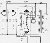
Here is how it is done, the correct way;
The feedback loop on the cathodes are on the correct side of the transformer and away from any possibiity od shock hazard if a valve fails.
Here is how it is done, the correct way;
The feedback loop on the cathodes are on the correct side of the transformer and away from any possibiity od shock hazard if a valve fails.
Attachments
1. The first thing I noticed is that the 6550 grids are connected to grid stoppers, and the grid stoppers are connected to the coupling caps.
No DC return, and No DC bias to the grids.
Your schematic is either inaccurate and incomplete . . .
Or the 6550s that do not have grid resistors to the grid bias circuit are going to go up in smoke!
Check all the wiring again, and make sure your schematic is both complete and accurate.
2. The wire windings of an output transformer secondary, common, 4, 8, 16, are much less than 1 Ohm (to prevent power loss, poor damping factor, etc.)
So if a 6550 plate to cathode short can burn out the A431 secondary wires, then the Dyna secondary wire was too fine (I seriously doubt that).
60 Watts into 8 Ohms . . . 2.74 Amps RMS, 3.87 Amps Peak.
Just how long can we expect the B+ to supply 2.74 Amps?
3. The cathode primary windings in a McIntosh output transformer are fine wire. They might possibly burn out if there is a plate to cathode short.
Last edited:
According to your schematic, the grid of the upper 6550 is driven from B2+, not the plate of the input tube. Is that correct?
The 1R2 resistor from OPT secondary to ground was likely intended as a bias current measuring point. This was convenient, no holes, free, but for safety's sake needs to be able to survive the current from a primary winding to secondary winding failure, and still blow the fuse. To modern eyes this is too twitchy and not safe enough. Separate small resistors in each output valve's cathode, maybe 10R or so, would give a better picture of output valve currents. Then the 4 Ohm tap goes straight to signal ground.
This kind of cathode feedback was popularized by Audio Research from the 1970s forward. It's only a tiny amount, a coupla dB, but easy and free, and in a good location. The driver circuit hasn't enough open loop gain for the long-loop feedback to do much, but that's in the "modern" idiom, so not open to criticism.
All good fortune,
Chris
The upper 6550 will have no signal on its grid.Hi all. Picked up a pair of Dynaco Mk3 for refurb. Didn't pay too much attention to the driver boards. I have seen so many of them over the years, that I can't keep track (stock circuit, 1 tube). Well... I hadn't seen this one. I drew it up to share (neg bias deleted for space). I figure they are individual made, someone's great idea🙄. But the implementation of a ccs, both amps having matching boards, and the cathode feedback with grounding through the secondary...Has anyone else ever seen this particular topology being used for a Mkiii, or anything else? I feel like I always see drivers after the ltp, if and when it is the first stage, and that the cathode feedback scheme looks shady as well...🤷🏼♂️

Partial cathode coupling of the output stage was done for many years by Bill Johnson at Electronic Industries and
Audio Research Corp, using 6550 GE tubes in all of their tube power amplifiers. Never a problem in any units I have seen.
ARC preferred to use 10R or 1R at the cathodes, rather than a sense resistor between the 4 ohm tap and ground.
And yes, the schematic has a mistake on the input stage connection to the output tube.
6A3 sorry about the bias. I mentioned it in the post knowing I had left it out. The schematic was really just something I drew up to see if anyone remembered an article, an old board...it reminds me of something someone saw in a magazine. Or maybe rather half of what they saw haha, albeit without the input tube. I agree on the secondaries handling it, still not my favorite.
Jon I agree. I have used cathode feedback before--from a feedback winding such as that.
Agreed Chris. Seems a fuse there would always be a good idea. And yes separate cathode Rs would definitely be better, especially when the amp has no dc balance control. But even if all were well, wouldn't directly grounding the 4ohm tap and then using 0,8 or 0,16 in this slight feedback arrangement, wouldn't it change the feedback response? I.e. one could not just do this to a circuit, while keeping original feedback circuit values for the front end feedback?
Mbrennwa, egellings and rayma- your absolutely right, not the way I drew it it wouldn't 🤦♂️ I was too focused on this strange setup and didn't notice my mistake, apologies. Now I can't edit, and that's what I get.
So I'm taking it that no one has seen this attempt elsewhere, that it was a one-off by some well intentioned hobbyist. The cathode feedback cheat is something interesting to think about, I haven't looked at any of those designs for a while. But regardless nothing is being done with these until I rebuild them. I see the Tubes4HiFi, Triode store, Curcio, and Pavel's autobias boards. I want to retain some resale value so I'll probably go with one of these known boards.
You can see something similar in Dave Gillespie's modification of the Heathkit W5, at comment #15. He does an excellent job of explaining the concept:
https://audiokarma.org/forums/index.php?threads/untapped-potential-heaths-w-5m.1042474/
The only caveat is that the output transformer must exhibit identical performance from each tap, which is the case with the W5's Peerless, and is probably also true of the Dynaco outputs.
https://audiokarma.org/forums/index.php?threads/untapped-potential-heaths-w-5m.1042474/
The only caveat is that the output transformer must exhibit identical performance from each tap, which is the case with the W5's Peerless, and is probably also true of the Dynaco outputs.
An interesting question, and I'd guess that a too broad answer should be no, but for most "hi-fi" amplifiers, it should be yes, it's possible and safe to try. Results are a tradeoff between some nice local feedback, right where you'd want it for output stage distortion, no stability issues, vs. a few dB higher driving voltage and that effect on driver distortion. Driven capacitance is decreased in proportion to feedback, so slewing current required doesn't change (!).wouldn't it change the feedback response? I.e. one could not just do this to a circuit, while keeping original feedback circuit values for the front end feedback?
Seems a much better approach to output stage local feedback than the incorrectly called, but popular, "Schade feedback" that heavily loads the driver full spectrum. (This is voltage sensing, parallel applied negative feedback, anode to grid - O. H. Schade's early 30s paper actually described a voltage sensing, series applied negative feedback, which the above cathode feedback actually is. But nobody cares.)
All good fortune,
Chris
Suppose the Common tap to 4 tap, is well matched to the 4 tap to 16 Ohm tap (that is what you want if you ground 4, and connect common and 16 to the output tube cathodes.
Suppose the old global negative feedback came from the 16 Ohm tap.
Just change the values of the parallel resistor & capacitor that come from the 16 Ohm tap (and the other ends back to the negative feedback node).
The feedback voltage is 0.707 of what it used to be. Therefore, reduce the resistor value by 0.707, and increase the capacitor value by 1.414.
That will usually work out perfectly.
I have followed this thread and is surprised that no one suggested the easiest and safest way to obtain a good well-documented amp : rebuild to original design and create a real Dynaco MkIII.
Yeah, for the question of long-loop stability a reasonable estimate would be that a few dB decrease in open loop gain (in any reasonably "hi-fi" amplifier) would contribute to stability margin significantly more than that small loop's added pole would reduce the margin.
Lots of folk, including me, have done this lots, with no drama. Safe and easy enough to try, IME/IMO. Can also be done to SETs and other modern amps - even less effect (lower Gm), but maybe worth trying.
All good fortune,
Chris
Lots of folk, including me, have done this lots, with no drama. Safe and easy enough to try, IME/IMO. Can also be done to SETs and other modern amps - even less effect (lower Gm), but maybe worth trying.
All good fortune,
Chris
Safety is in the eye of the beholder.
Be sure your Hernia Insurance is Paid Up.
Be sure to use KT88s, the 6550 might go up in smoke (especially some modern ones).
You do not want to have to modify the amplifier driver to be able to drive the new 50k Rg resistor values for the 6550 tubes (new driver circuit, and the coupling cap value has to double).
I once had a 6550 Red-Plate. Not pretty.
Thank you Grover. I also see in his schematic that the connection is 16>cathode>input. On this one it was 2 wires and I'd want to clean that up.
6A3- I understand what you are saying about the reduction in global feedback as for the amount of value change needed. But why is it .707? The global is still coming from the 16ohm tap, so is it .707 because now the local feedback we're introducing is taking away from the original amount available on the 16?
Chris- Good point on the slewing current, thank you. And I know some of us care 😉
But no matter what you call it, yes plate to grid feedback is another thing I want to try. I might start out with that last kt88 amp I built last year with y'all's help 🙏.
Peter- I agree, that is the safest and easiest way to make a documented amp. This started because I genuinely was curious if anyone had seen this particular "mod" (travesty) before. Apparently not, but regardless it becomes informative and interesting to see what is said about it. I have considered restoring these. But I think we all know about some of the cost cutting on these commercial amps. I'm more fond of my music than nostalgia or resale. When I decide, I'll start a different thread for the rebuild and document everything. Speaking of which, can anyone point me to any other designs utilizing the mkiii chassis and iron? I know there's a ton out there, but I'm yet to see anything with different output valves, voltage regulation, heck even the cathode feedback we're discussing....
Thank you for the continued input 🙏
-Loren
The .707 number was a slip - signal voltage is actually reduced by half, so feedback resistor is halved and lead capacitor is doubled, to keep the same closed loop gain. Loop gain is decreased by the amount of local feedback, usually a few dB at most.
There are lots of issues to be faced to make a Type III operate reliably with modern (higher) mains voltages and modern (much poorer) output valves and horrible modern rectifier valves. There's no room for anything heroic, so a lot of subtlety is called for. Probably want to start by reducing B+, individual bias adjustments, "yellow sheet mods" for rectifiers, all the Best Practice stuff.
All good fortune,
Chris
Agreed Chris. I'm thinking about getting a pair of the tubes4hifi boards. Same topology as that kt88 amp I was talking about actually, and most likely that's what I'd choose here anyway. One thing I personally haven't learned is how to make and send off PCB designs, and I do like the idea of keeping things tidy here.
I also plan on getting B+ down a bit from the current 550vdc. I'll probably take it back to VT rectification (these had diode bypass), so I shouldn't be too far off. I figure 500v area should be fine if I'm biasing them around 65ma, even with most of the newer tubes? Maybe I'll see what I have for other chokes...
I also thought about dropping those volts with a regulator, and going slow start. But it starts to take up space I don't have, and I'm not to go that route at all if I can't regulate B+ as well as bias supplies. Most likely it'll be tube, with the PIV modification (I assume that's the yellow sheet)
Loren
Factory original was rated +480 VDC with 115 VAC mains and Genalex output valves at $12US for factory matched pairs. I've become very conservative these days by bitter experience. Capacitor voltage is also a challenge, but I can highly recommend an outfit called Hayseed Hamfest, who custom makes can caps in beautiful stainless-looking cans with Nichicon 105C caps inside, up to 500 VDC rating and Ham not Audiophile prices.I figure 500v area should be fine if I'm biasing them around 65ma, even with most of the newer tubes?
All good fortune,
Chris
kb2wyl and Chris Hornbeck,
Yes, another slip of my brain calculator.
1. Non traditional output connections (4 Ohm tap grounded):
So for ease of discussion . . .
With Common at ground:
16 Ohm tap 1.0V
8 Ohm tap 0.707V
4 Ohm Tap 0.5V
Common 0V
Changing the ground connection:
With the 4 Ohm tap grounded, we have . . .
16 Ohm tap 0.5v
Common 0.5V opposite phase.
If the global negative feed back was on the 16 Ohm and you keep it connected to the 16 Ohm tap then . . .
When the 4 Ohm tap is connected to Ground, Reduce the negative feedback resistor to 0.5 its original value, and multiply the capacitance by 2X.
That takes car of the cathode feedback example.
2. For traditional output connections, with Common at Ground . . .
For those who do not want the global negative feedback to come from the 16 Ohm tap, instead they want the global negative feedback to come from where they connect their speaker:
Moving feedback from 16 Ohm tap to the 8 Ohm tap . . .
Reduce the feedback resistor to 0.7 its original value; and increase the capacitor by 1.4 times its original value.
Moving feedback from 16 Ohm tap to the 4 Ohm tap . . .
Reduce the feedback resistor to 0.5 its original value; and increase the capacitor by 2 times its original value.
3. I think I got all cases of grounding, and feedback connections correct this time.
As always . . . you guys need to check my work.
Thanks!
- Home
- Amplifiers
- Tubes / Valves
- Have you ever seen this done to a MkIII?