Does anyone know of a good headphone amplifier project or kit that is based on a discrete A/B output stage and includes negative feedback of the output signal in order to reduce crossover distortion? I need something beefy as my target is to drive some demanding planar headphones
Last edited:
Just buffer a descent op-amp and it should be plenty for headphones. Or you could throw together a modest "blameless" circuit. I approve your choice of a A/B output. Most "headphone amps" I see on DIYA are over built, poor class-A designs that reflect the limitations of the designer and not any kind of performance. Note that TI makes a number of headphone amp chips (see their web site), but my choice would be to avoid any kind of proprietary parts.

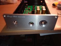
The Omicron is the way to go if you ask me. It has a discrete A/B output stage and includes (lots of) negative feedback of the output signal in order to reduce all kinds of distortion. It has been built by many by now and proved to be an excellent headamp on both measurements and audition.
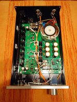
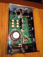
If you need more power, have a look at the Krell KSA-5 clone with my mods. It is not as good as the Omicron, but it can drive normal loudspeakers and sounds pretty decent. The gerbers of the (original) PCBs are available, BTW.

by Rod Elliott:

by Silicon Chip and Everyday Practical Electronics:

and probably by others. It works, but its performance is limited, so don't expect miracles.
If you need more power, have a look at the Krell KSA-5 clone with my mods. It is not as good as the Omicron, but it can drive normal loudspeakers and sounds pretty decent. The gerbers of the (original) PCBs are available, BTW.
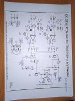
That's the headlamp that has been floating around for long time. For example, it has been published by Douglas Self in hiss Small Signal Audio Design:buffer a descent op-amp and it should be plenty for headphones
by Rod Elliott:
by Silicon Chip and Everyday Practical Electronics:
and probably by others. It works, but its performance is limited, so don't expect miracles.
Last edited:
Most "headphone amps" I see on DIYA are over built, poor class-A designs that reflect the limitations of the designer and not any kind of performance.
For portable applications, sure, but for a desktop there are some good reasons to overbuild:
The higher the idle current w.r.t. signal current, the lower the modulation, so that improves temperature stability, transconductance stability, etc. Similarly, stretching the drain voltage as high as practical also reduces the signal amplitude w.r.t. idle Vds.
Even something like 30V rails x 100mA is just 3W, not much in the scheme of things. Or 200mA -- 6W, and could be powered by a phone charger with a suitable boost circuit. A metal case may keep a coffee cup tepid, maybe slightly warm. Too much noise? Drop a spare 4V across an LM317, and the 400mW will not be noticed.
Optimising by changing a CCS load to a complementary MOSFET seems like a solution to a non-existent problem. And while you are at it, the PSU no longer sees a constant load, but it now has to prevent distorted audio from modulating the rails. So the complexity spirals.
@alexcp Thanks for posting these circuits. The first two look similar to the Omicron. Is the Omicron superior to these? If so, what do you think makes it better.The Omicron is the way to go if you ask me. It has a discrete A/B output stage and includes (lots of) negative feedback of the output signal in order to reduce all kinds of distortion. It has been built by many by now and proved to be an excellent headamp on both measurements and audition.
If you need more power, have a look at the Krell KSA-5 clone with my mods. It is not as good as the Omicron, but it can drive normal loudspeakers and sounds pretty decent. The gerbers of the (original) PCBs are available, BTW.
That's the headlamp that has been floating around for long time. For example, it has been published by Douglas Self in hiss Small Signal Audio Design:
View attachment 1347304
by Rod Elliott:
View attachment 1347309
by Silicon Chip and Everyday Practical Electronics:
View attachment 1347310
and probably by others. It works, but its performance is limited, so don't expect miracles.
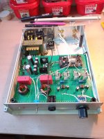
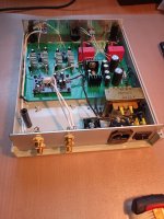
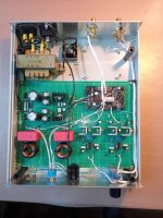
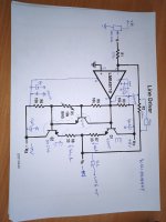
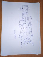
Or something like this, a little simpler and cheaper. Quiescent current is 30mA. It can be more, with a stronger power supply and bigger coolers. A non-inverting schematic can also be used. The power supply is 7815/7915. DC protection is by @miro1360. A higher supply voltage can be used, up to the OPA limit. Other (stronger) output transistors can be used, I had these available in matched pairs. Compensation must be adjusted for each OPA and output transistors (10pF or more). For awkward loads (capacitive) Zobel compensation may have to be added to the output.
Attachments
Last edited:
Yes!Is the Omicron superior to these?
(Depending on what you define as "superior", if course)
Much more open loop gain, more negative feedback and less distortion.If so, what do you think makes it better.
Ah, they all look similar - there is an opamp at the input and a complementary emitter (or source) follower at the output.The first two look similar to the Omicron
The main difference is that the Omicron is a composite amplifier (that is, its two opamps work in a single feedback loop). Because of that, Omicron has at least two orders of magnitute more loop gain and proportionaly less measured distortion. (Thank you @stv!)
There is a school of thought that says the amplifier's distortion below a certain threshold is unimportant (inaudible, masked by the distortion of the source/cans/something else, etc.). However, the difference has been very much audible to quite a few people, some of them quoted in the first post of the Omicron thread.
OPA1622 is an easy solution for portables, also for planar.
And of course Class AB, as requested.
https://www.diyaudio.com/community/threads/new-audio-op-amp-opa1622.283672/post-4747938
https://www.diyaudio.com/community/threads/new-audio-op-amp-opa1622.283672/post-4789925
https://www.diyaudio.com/community/threads/new-audio-op-amp-opa1622.283672/post-4953256
🙂
Patrick
"With an impedance of 50 Ω and a sensitivity of just 83 dB, the HE6SE v2 are very hard to drive and require lots of power: they need ~1.4 W to get to 115 dB..... At 115 dB, you get permanently deaf to some (or even all) frequencies after less than 30 seconds"
https://www.soundphilereview.com/reviews/hifiman-he6se-v2-review-11850/
A LM1875 with +/-20V rails will give you 2W into 50R, and Class AB.
http://kit-amp.com/lm1875-testing
Patrick
https://www.soundphilereview.com/reviews/hifiman-he6se-v2-review-11850/
A LM1875 with +/-20V rails will give you 2W into 50R, and Class AB.
http://kit-amp.com/lm1875-testing
Patrick
Last edited:
Neurochrome rated the hat with OPA1622EVM 360mW for 50Ω, < 0.01 % THD+N.@yys310 Ideally 2W per channel,
Seems that it won't reach the output you desire but still worth trying...the OPA1622EVM from TI only costs ~25USD.
https://www.tij.co.jp/jp/lit/ds/symlink/tpa6120a2.pdf
You can obtain ~1.4W RMS @+/-15V power supply with an incredible performance. And you need only 1 IC.
And if you can use bridge mode (difficult for phone) with 2two IC's you will have a lot of power.
I use the phone output of my DAC (phone amplifier is TPA6210A2) to power standard multichannel speakers for impedance measurement and not only for this.
- Home
- Amplifiers
- Headphone Systems
- Headphone amplifier based on class AB with feedback