I’ve been reading up trying to figure out how to measure transistor Ft. I currently have three transistor testers, Peak Atlas DCA75 which I use for gain matching and checking overall health of the transistor, a Heathkit IT-3121 that has been fully restored, and a Hickok model 440 that has been fully restored. I don’t think any of these will get me Ft.
I’m not wanting to measure extremely high, maybe 120 MHz max, maybe 150. My oscilloscope is a Rigol DS1102E which is a 100 MHz scope, but if I need X-Y function I don’t think it has that. I do also have a Tek 7603 with a pair of 7A18 modules (75 MHz) and a 7B53 triggering module. I do plan on upgrading my digital scope soon though. I have a signal generator that will go to 2 GHz.
I have found small snippets of info, but nothing concrete on how it’s done.


I’m wondering if these statements can get me started. I figure it would be a good skill to learn to, if nothing, root out fake devices and help determine unknown devices.
Thank you,
Dan
I’m not wanting to measure extremely high, maybe 120 MHz max, maybe 150. My oscilloscope is a Rigol DS1102E which is a 100 MHz scope, but if I need X-Y function I don’t think it has that. I do also have a Tek 7603 with a pair of 7A18 modules (75 MHz) and a 7B53 triggering module. I do plan on upgrading my digital scope soon though. I have a signal generator that will go to 2 GHz.
I have found small snippets of info, but nothing concrete on how it’s done.
I’m wondering if these statements can get me started. I figure it would be a good skill to learn to, if nothing, root out fake devices and help determine unknown devices.
Thank you,
Dan


Not related exactly, but I think you do have XY for future ref. Just go to the menu for horizontal and select XY for time base.
Haha, awesome! Thank you for the info. I had no idea.Not related exactly, but I think you do have XY for future ref. Just go to the menu for horizontal and select XY for time base.
This is the thing to buy, used. They quit making them new, several years ago.
Oh awesome, I had no idea that even existed. I will very likely pick one of these up, but what would be the proper method without this device? let’s say I wanted to measure some transistors in the next day or two and didn’t want to have to wait until this tester arrived to me.
Dan
Pages 24 and 25 of the BK Precision owner's manual discuss the way their instrument measures fT. You could design and build your own hardware to work the same way.
Then pages 38 and 39 of the BK Precision owner's manual discuss the theory of fT and putting that theory into practice.
All four of those pages are collected into a single Acrobat .pdf file, which is attached to post #2 of this thread. You can read them right now if you like.
Then pages 38 and 39 of the BK Precision owner's manual discuss the theory of fT and putting that theory into practice.
All four of those pages are collected into a single Acrobat .pdf file, which is attached to post #2 of this thread. You can read them right now if you like.
Pages 24 and 25 of the BK Precision owner's manual discuss the way their instrument measures fT. You could design and build your own hardware to work the same way.
Then pages 38 and 39 of the BK Precision owner's manual discuss the theory of fT and putting that theory into practice.
All four of those pages are collected into a single Acrobat .pdf file, which is attached to post #2 of this thread. You can read them right now if you like.
Oh excellent, thank you!
Dan
Very interesting thread!
I can still find interesting old stock transistors and would like to have the capability for these kinds of measurements, including early voltage and quasi-sat behaviour (like Mark Johnson has been measuring, very useful - thanks).
I can still find interesting old stock transistors and would like to have the capability for these kinds of measurements, including early voltage and quasi-sat behaviour (like Mark Johnson has been measuring, very useful - thanks).
I can’t get enough info (ie, I’m not skilled enough) to come up with a schematic with the info provided on the pages. Here it is for everyone else.

Like choosing the auto biasing IC, buffer, amp, detector. Above my head.
For some reason, I was thinking there was a way to use a power supply, signal generator, and a scope to see where amplification stops. I love it when I can find a neat little schematic like Nelson’s jfet and mosfet matcher. Whipped it up and then measuring across a resistor I was able to Idss match fets.
Dan
I have a home-built Ft-meter based on first principles (emitter current is modulated and the resulting base and collector are measured and compared). Vce and Ic can be set over a wide range, and the maximum frequency is in excess of 1GHz (extrapolated), but it is a big, complicated kludge, designed and built before the electronic documentation era, meaning it would be difficult to share and reproduce, unfortunately
I have a home-built Ft-meter based on first principles (emitter current is modulated and the resulting base and collector are measured and compared). Vce and Ic can be set over a wide range, and the maximum frequency is in excess of 1GHz (extrapolated), but it is a big, complicated kludge, designed and built before the electronic documentation era, meaning it would be difficult to share and reproduce, unfortunately
Thank you for sharing.
Dan
I can try to dig my paper archives, and scan whatever I deem usable, but I promise nothing: it was a long time ago, and the documentation was meant for my own use, just to make the thing work.Thank you for sharing
I am not even sure I can still make sense of what I wrote ~25yrs ago.
I'll try, anyway but the principles are sound and universal and can be reused in a more modern instrument. IIRC, the main difficulty was the need to accommodate both polarities, switch the current and voltage ranges, etc. If you just want to measure a single transistor for a fixed set of conditions, you can probably get away with just regular lab instruments and some ingenuity.
Making a universal instrument is much more painstaking.
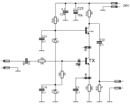
Since you seem to have a scope with sufficient bandwidth, do you have a generator capable of generating a square wave of several hundred kHz?My oscilloscope is a Rigol DS1102E which is a 100 MHz scope
If you have one, you can measure ft using the following procedure with a relatively simple circuit.
1. set the collector current by adjusting VR1.
2. apply a square wave to the input (probe 1) and adjust the value of R2 (actually a trim pot) so that the output waveform (probe 2) is a square wave - a similar procedure to adjusting the probe on a 10:1 oscilloscope.
3. read the input amplitude Vin and output amplitude Vo on the scope.
4. determine Ft using the following equation.
Ft = (1/(2*πC1*R1))(Vo/Vin)
Note that there is no "Ft" in the model parameters in SPICE, but the forward transition time "TF" is specified.
Since TF = 1/(2*π*Ft)
The TF can be calculated as follows.
TF = C1*R1*(Vin/Vo)
Specific steps are shown on the simulation using the 2N2222 model as DUT.
1. aiming for a measured collector current of 20 mA, VR1 was adjusted to 20 mA at the 27.7% position. In the actual measurement, measure the voltage at both ends of R1 with a DMM.
2. add a 500 kHz 100 mVpp square wave to the input. Adjust the value of R2 while checking the output waveform: if R2 is 6 kΩ, the rising and falling edges overshoot;
if R2 is 4.5 kΩ, the rising and falling edges round off;
if R2 is 5.23 kΩ, the output waveform is a clean square wave.
3. The output amplitude at this time was 78.6 mVpp.
4. Ft = (1/(2*π*20p*20))(78.6m/100m) = 312.7MHz.
TF = 20p*20*(100m/78.6m) = 0.509nsec.
I checked the parameters for my 2N2222 model and found TF = 4.00E-8 i.e. 0.4nsec.
This difference could be reduced by increasing the collector current value a little more. However, be aware of the heat generated by the DUT in the actual measurement.
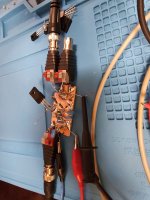
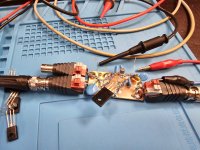
I built and used a board for this measurement almost 20 years ago. The left one is for NPN and the right one for PNP. The traces on the boards are exactly the same, only the polarity of the power supply and electrolytic capacitors is different.
R1 uses a plate resistor with low inductance, but SMD is better. Due to the availability of parts on hand at the time of production, 20pF seems to use two 10pF SMDs. (It was a long time ago, so I don't have a very accurate memory.) If it is a circuit of this level, I think it is possible to produce it with a perfboard.
Last edited:
I managed to retrieve some material; not very usable, but better than nothing.
First, here is "The Thing":

The PDF consists of a general concept (first page), the detailed schematic, and some additional notes.
The instrument is in fact made of two separate sections sharing common supplies, controls and indication. One is for HF/VHF up to 350MHz (extrapolated) and requires an external generator, the other is for UHF, up to 1.5GHz and has its own generator, but a more limited set of Vce/Ic conditions.
First, here is "The Thing":
The PDF consists of a general concept (first page), the detailed schematic, and some additional notes.
The instrument is in fact made of two separate sections sharing common supplies, controls and indication. One is for HF/VHF up to 350MHz (extrapolated) and requires an external generator, the other is for UHF, up to 1.5GHz and has its own generator, but a more limited set of Vce/Ic conditions.
Attachments
Since you seem to have a scope with sufficient bandwidth, do you have a generator capable of generating a square wave of several hundred kHz?
If you have one, you can measure ft using the following procedure with a relatively simple circuit.
View attachment 1340776
1. set the collector current by adjusting VR1.
2. apply a square wave to the input (probe 1) and adjust the value of R2 (actually a trim pot) so that the output waveform (probe 2) is a square wave - a similar procedure to adjusting the probe on a 10:1 oscilloscope.
3. read the input amplitude Vin and output amplitude Vo on the scope.
4. determine Ft using the following equation.
Ft = (1/(2*πC1*R1))(Vo/Vin)
Note that there is no "Ft" in the model parameters in SPICE, but the forward transition time "TF" is specified.
Since TF = 1/(2*π*Ft)
The TF can be calculated as follows.
TF = C1*R1*(Vin/Vo)
Specific steps are shown on the simulation using the 2N2222 model as DUT.
1. aiming for a measured collector current of 20 mA, VR1 was adjusted to 20 mA at the 27.7% position. In the actual measurement, measure the voltage at both ends of R1 with a DMM.
2. add a 500 kHz 100 mVpp square wave to the input. Adjust the value of R2 while checking the output waveform: if R2 is 6 kΩ, the rising and falling edges overshoot;
View attachment 1340777
if R2 is 4.5 kΩ, the rising and falling edges round off;
View attachment 1340778
if R2 is 5.23 kΩ, the output waveform is a clean square wave.
View attachment 1340779
3. The output amplitude at this time was 78.6 mVpp.
4. Ft = (1/(2*π*20p*20))(78.6m/100m) = 312.7MHz.
TF = 20p*20*(100m/78.6m) = 0.509nsec.
I checked the parameters for my 2N2222 model and found TF = 4.00E-8 i.e. 0.4nsec.
This difference could be reduced by increasing the collector current value a little more. However, be aware of the heat generated by the DUT in the actual measurement.
I built and used a board for this measurement almost 20 years ago. The left one is for NPN and the right one for PNP. The traces on the boards are exactly the same, only the polarity of the power supply and electrolytic capacitors is different.
View attachment 1340780
View attachment 1340781(Some differences from the circuit diagram above)
R1 uses a plate resistor with low inductance, but SMD is better. Due to the availability of parts on hand at the time of production, 20pF seems to use two 10pF SMDs. (It was a long time ago, so I don't have a very accurate memory.) If it is a circuit of this level, I think it is possible to produce it with a perfboard.
Awesome! Something like this is exactly what I was looking for. You say certain components are better being SMD, with the circuit as a whole be better if it wasn’t entirely SMD?
Dan
Seems simpler than i thought (if you know the math & hve proper instruments). But I feel inspired by Mr. Elvees version. Lot's of hardwork. Highest degree of passion & enthusiasm.
Regards to both 😊
Regards to both 😊
with the circuit as a whole be better if it wasn’t entirely SMD?
SMD is only desirable in low resistance areas, such as load resistor R1. This is because at low resistance values it may not be possible to reproduce a clean square wave due to parasitic inductance effects. My board has an input attenuator, which is not shown in the circuit diagram, and its resistance value is also low, so I use a plate resistor. Other precautions are to keep the impedance of the power supply low to high frequencies (0.1uF SMD ceramic CAP + OS-CON near R1) and to use a small trim pot for R2 to reduce parasitic capacitance.
The circuit diagram of the actual board is attached for reference.
These values are suitable for measuring BJTs for small signals. When measuring BJTs for high currents, a larger value for C1 and lower values for R1 and other resistors would be desirable.
Interesting thread.
I was just looking for some information about it and found this.
I was wandering if measuring the Ft of the original transistor and comparing it to the supposed original one would help figure out if the new "original" is real or fake.
It just crossed my mind.
Would be using something more modern like a spectrum analyzer and a tracking generator be a better option?
Based on the BK_precision_530 documentation, I also designed a measurement scheme for Ft. The beta amplification factor in cc is determined by measuring the voltages on Re and Rb respectively. After that a sinusoidal signal of 100 Khz is applied to the input and the value of the output voltage is noted. We increase the frequency of the input signal until a value at which the amplitude of the output signal decreases to about 0.7 of the value of the output signal at 100 Khz. This is how we get Fc. After which Ft=beta x Fc.
Attachments
Very nice, congratulations @akosboros ! A cute idea to use the super high fT switching transistor 2N2369 in the cascode position. It appears that measurements are taken at Ice = 10mA and Vce = 10V (?)
- Home
- Amplifiers
- Solid State
- Measuring transistor parameters, specifically Ft