Greetings,
I would like to share an idea of an audio amplifier that I wanted to develop for my home speakers.
The target is to build a 200W Circlotron with the following guidelines:
- Zero global feedback
- Same N polarity output devices: for a wider range of output devices including IGBT.
- PnP auto bias: no need to adjust bias even when swapping output devices between BJT, MOSFET (Enhanced) and IGBT.
- No thermal tracking.
- Output devices never switch off: no switching crossover distortion with low idle current and no transconductance doubling.
- Symmetric and flat output impedance.
- Modular: swappable voltage stage, driver stage and power stage boards.
This is the start, with the follower power stage section as in the picture.
It will follow the gain stage with different solutions:
- DC coupling: more challenging and it may require DC servo.
- Capacitor coupling.
- Interstage transformer coupling with tubes.
I wish that people interested in this project will enjoy all contributions and have a complete ownership of the results in the DIY community.
As it was done under the top cover of the Commodore Amiga 1000, I wish to print names or signatures on the future PCB boards.
Thanks to Kendall and Cordell
Alfonso Pelizzo
Last edited:
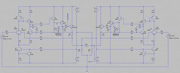
I attached the asc file of the class i circlotron as an example.
Q10 and Q20 can be changed to MOSFET or parallel BJT according to preference and targets.
If you wish to drop variation of the schematic, could you please increase the number at the end of the filename. Eg Class_i schematic_02.asc ,03, 04 etc. It will be easier to track them
Q10 and Q20 can be changed to MOSFET or parallel BJT according to preference and targets.
If you wish to drop variation of the schematic, could you please increase the number at the end of the filename. Eg Class_i schematic_02.asc ,03, 04 etc. It will be easier to track them
Attachments
HI !
Thanks for this buffer !
I woud like made it with BJT output and BJT voltage amp
Could you share the asc with my voltage amp like the thread ?
Thanks for this buffer !
I woud like made it with BJT output and BJT voltage amp
Could you share the asc with my voltage amp like the thread ?
Hi, Alfonso!
Very good indeed.
Two shoulders of Kendall Castor-Perry class-I LTPs followed with output triple.
Some thoughts.
First. Output triple.
It needs special attention to become stable. 100 Ohm last stage base stopper not a best choise.
Second. Input.
The OPS itself becomes differential since outputs aren't referenced to ground. So you can easily put any FDA like OPA1632 or THS4131 in front of it.
Third. Output point.
Since bias current are set automatically you need to regulate or manage output null voltage and output common-mode voltage.
Fourth. Input and output common-mode noise.
Since we're fully-differential we sensitive to previous source hot and cold impedances imbalance. At the output we can use simple common mode choke while at the input we need to put first instrumentation amp, may be with single-ended output and volume regulation stage, then working point setup circuitry (integrator and output common-mode control) next FDA followed with output stage.
Fifth. Supply.
Parasitic interwinding capasitance at the power supply trafo becomes OPS load limiting bandwidth. So it will be good to use LLC SMPS with dedicated floating windings.
So it will be good to use LLC SMPS with dedicated floating windings.
HI
Do you have an exemple ?
thanks
HI !
Thanks for this buffer !
I woud like made it with BJT output and BJT voltage amp
Could you share the asc with my voltage amp like the thread ?
Hi there,
I know you are working on your next Circlotron without global feedback.
I am still playing with the schematics so the stopper resistor at the base of the BJT was because I was playing with a mosfet.
The schematic is not refined yet.
Attachments
Hi, Alfonso!
Very good indeed.
Two shoulders of Kendall Castor-Perry class-I LTPs followed with output triple.
Hi BesPav !
Thanks for sharing your engineering. Please feel free to edit the schematic if you wish. When we get to certain point when we have a number of ideas from other people we can narrow down and start merging good solutions.
Yes sorry, the schematic is not definitive. I had 100 Ohms because I swapped with a mosfet earlier. IanHegglun told me and changed to 10 Ohms for BJTSome thoughts.
First. Output triple.
It needs special attention to become stable. 100 Ohm last stage base stopper not a best choise.
Would the OPA have enough voltage swing? My target is to reach 40V swing output (+/-20). Also the input source should be a little low impedance to overcome some nonlinearities due to the doublet.Second. Input.
The OPS itself becomes differential since outputs aren't referenced to ground. So you can easily put any FDA like OPA1632 or THS4131 in front of it.
The output will be zero volts as long as the input is at zero volts exactly. And that is critical. Any voltage offset at the input will quickly lift the idle current and that is dangerous. Transformer coupling would be the simplest, safest and easy way to keep the inputs balanced.Third. Output point.
Since bias current are set automatically you need to regulate or manage output null voltage and output common-mode voltage.
Fourth. Input and output common-mode noise.
Since we're fully-differential we sensitive to previous source hot and cold impedances imbalance. At the output we can use simple common mode choke while at the input we need to put first instrumentation amp, may be with single-ended output and volume regulation stage, then working point setup circuitry (integrator and output common-mode control) next FDA followed with output stage.
Fifth. Supply.
Parasitic interwinding capasitance at the power supply trafo becomes OPS load limiting bandwidth. So it will be good to use LLC SMPS with dedicated floating windings.
For the Fifth point I thought about the effect of interwinding capacitance. I would use two separate transformers. Eventually in a stereo configuration we could use two secondary windings from one transformer for the L/R hot and the other transformer for the L/R cold.
Last edited:
for my next one I think I will use 4 separate transformer or... 4 SMPS, but I have not yet found these smps
Last edited:
UltimateX86, I like your voltage stage and we need to think about how to keep the outputs stable at zero volts in idle if you want DC coupled to the power stage. DC servo?
After a few prototypes and tests this a board for one channel. This is the fully solid state version. All the initial goals have been reached. Above all the sound...


Fascinating concept and build! Any output distortion measurements? Regardless, it looks great. An ambitious project. 👍
I have been working about three years on this project with many hundreds hours of listening. The first sample already had a very transparent sound but I wanted to improve it in terms of noise and distortion. It has been quite challenging because it's a fully differential design and without global negative feedback. I believe it has a very distinctive sound. In other amplifier I listened, I found that instruments tend to hide behind others during the reproduction. But this one manages to see all of them. So it has a very stable sound image. I really got addicted. The design concept resembles the Russian Vityaz DT30: (VAS-REG-PSU) - (PWR-DRV-PSU).
The design concept resembles the Russian Vityaz DT30: (VAS-REG-PSU) - (PWR-DRV-PSU).
This one?
- Home
- Amplifiers
- Solid State
- Class i Zero Global Feedback Circlotron 200W