hbc,
You said:
"comparing BD139 and ECC88, measured distortion was similar but different. As similarly rated devices, I had a circuit where I could easily interchange between them. Driving each one, common base / grid, the tube sounded significantly better than the transistor."
Common base / grid?
Did you drive the Emitter? And did you drive the Cathode?
Those are common base and common grid stages.
The input impedance is very low.
Or were the BD139 and ECC88 used in common Emitter and common Cathode mode?
Thanks!
The emitter / cathode, being driven directly by output of TDA1543, with base / grid adjusted to get the appropriate 2.3 ish volts required by the DAC.Or were the BD139 and ECC88 used in common Emitter and common Cathode mode?
hbc,
So you use a current source for the emitter/cathode;
adjustable bias voltage for the base/grid;
And you have equal collector/plate load resistors.
Is that correct?
I am not familiar with that DAC, but I am guessing it has a current output; which is converted to a voltage by the low impedance of the emitter/collector.
A low impedance that is required because of the maximum compliance voltage of the DAC.
Did I get it right?
Seems like a nice output stage for a current output DAC.
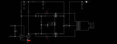
Yes that sounds about right. I have made several variants of the circuit over the years and I like it very much, this particular one drives a class A bipolar output stage to drive speaker directly.Seems like a nice output stage for a current output DAC.
Simplified circuit, the DAC / tube is on a rail about - 50 volts lower than the PNPs, not shown on this here, R3 is shunt volume control.
Doesn't the number of components to create equivalent circuits count for anything? The beauty of tube circuits is how simple they are. Isn't there some multiplicative or cumulative affect that is linked to the count of components that trumps other differences, such as linearity of the active component?

Dear Hector,
this is the internet, so sadly logic will get you nowhere. The primary reason valves are still attractive is that their sonic overload characteristics are a bit more benign than their transistor equivalents. If forum members spent as much time understanding that and then designing a circuit that had sufficient headroom to handle transients, then there'd be less desire to find that single magic golden eared component that makes all the difference and people might actually spend their time actually listening and enjoying their music, not their capacitors.
Just think "Monty Python and the Holy Grail" where our forum members are the ones on the quest and you are the bloke at the end of the rope bridge asking them whether it's the mean airspeed of a paper in oil capacitor or a polypropylene capacitor....
kind regards
Marek
In that case I am the one with no arms and no legs, complaining it is just a scratch ...Just think "Monty Python and the Holy Grail" where our forum members are the ones on the quest and you are the bloke at the end of the rope bridge asking them whether it's the mean airspeed of a paper in oil capacitor or a polypropylene capacitor....
Here are my 2c. The fundamental difference between SS and tubes is gain. SS devices tend to have a lot of gain. That translates to a small Vgs v Id area that is linear. Tubes have a relatively large linear Vgs v Id region (translates to less gain). How you use those properties best determines the outcome.
The subtle (or not so subtle) modulations probably do add up in many cases. Pass discussed this in an article, 2009-ish.Doesn't the number of components to create equivalent circuits count for anything? The beauty of tube circuits is how simple they are. Isn't there some multiplicative or cumulative affect that is linked to the count of components that trumps other differences, such as linearity of the active component?
Self denies there being any unique distortion mechanism of thermal effects per se, but at the same time promotes many optimizations that serendipitously also reduce thermal modulation. (He seems too sly. I just give away most of my ideas for free 😇.) One doesn't have to look very far: datasheets usually lay out some key differences between 25°C and 125°C, etc. And with minimal investigation, variable V-drop x variable current gives the power dissipated, leading to different junction temperatures and so on.
Btw, what's the temperature of the vacuum likely to be? Does it have any meaningful heat capacity in a tube? How good is the thermal connection between the glass case and tube-innards vs the junction/case of silicon?
I'm inclined to consider a few interesting cases for tubes:
Cascodes and folded cascodes, as glue logic between an input stage and output gate (common source MOSFET). All I really need is a 10:1 impedance conversion, so the voltage swing is divided down, as seen by the input stage, a bit like the M2x amplifier with its trafo in the middle. Failing that, small signal MOSFETs could work. But they also undergo heavy hot-cold modulation.
I also have a use-case to attenuate the signal 20:1, and invert it for mixed-mode feedback (source resistor fbk is opposite polarity to centre-tapped feedback) but if I use a whole op-amp for the 'simple' task of inversion, the amplifier speed degrades significantly.
With no restrictions on "optimization" can't you level the playing field anywhere you choose?In optimized conditions for each, which devices generally measures better - thd/gain/output impedance/etc
Certainly, you have to compare devices for a specific defined function, which would include many other, different parts.
Power amp, RIAA, etc.
Power amp, RIAA, etc.
OldHector,
You said:
"Doesn't the number of components to create equivalent circuits count for anything? The beauty of tube circuits is how simple they are. Isn't there some multiplicative or cumulative affect that is linked to the count of components that trumps other differences, such as linearity of the active component?"
. . . I agree, that is probably true in many cases.
Consider the linearity curves of each device.
With one after another in serial, they more or less add or cancel to some degree.
Are there times when it is more complex than that, with ripple(s) somewhere in the middle of the dynamic range of the total amplifier circuit?
Other kinds of similar additive/subtractive/rippling effects of multiple devices:
Most lenses have an amount of either barrel distortion or pincushion distortion.
But some lenses have complex distortion, with a ripple either in the middle, or partway from the middle to the corner of the field of coverage.
One of my favorite lenses: The Preset 1:1 50mm f4 Macro-Takumar.
It is one of the sharpest, one of the most contrasty, and one of the least flare prone lenses in my collection.
(I have not checked its Macro performance).
My point that relates to the number of amplifying devices in an amplifier:
. . . My Macro-Takumar is a Tessar design: Only 4 elements, in 3 groups.
Simple Works!
It performs pretty well versus some modern macro lenses that are 7 Elements in 6 Groups, or even 13 Elements in 10 Groups.
True, my Macro-Takumar is Manual Focus, and there are No Electronic Connections that allow the camera to control the aperture.
Last edited:
When it comes to Aesthetics, Mysticism and Spirituality, valves are unmatched. Those properties however, are hard to measure.
Exactly. Food for thought:Consider the linearity curves of each device.
With one after another in serial, they more or less add or cancel to some degree.
Are there times when it is more complex than that, with ripple(s) somewhere in the middle of the dynamic range of the total amplifier circuit?
Intermodulation is created whenever complex signals pass through an amplifying stage where there is some non-linearity. You can probably cancel some harmonics some of the time, by making the next gain stage bend in the opposite direction, but the IMD from the previous stage is treated as part of the signal, so you get "IMD² ". It could quickly devolve into noise, where the system starts to behave chaotically.
People may sometimes prefer 100ppm of simple harmonics and 1st order IMD, over 10ppm of "sawtooth" harmonics and n-th order IMD. It's a fake example, but 10:1 is 20dB difference and a common point of comparison. The old Fletcher-Munsen curves for hearing sensitivity span a lot more than 20dB, so one thing to check is that a design may be overly complex if it hastily trades a few low harmonics for 10s or 100s of higher harmonics where the ear is far more sensitive.
Interesting analogy that puts in perspective the applicationDo not use a Ball Peen Hammer to install Phillips Screws in wood.
Engineering is an Art and a Science.
Just my $0.03
OmeEd,
I did not say anything about: "Aesthetics, Mysticism and Spirituality"
Perhaps another Poster mentioned those things in this thread, I must have overlooked them when I read the posts..
Those generally are not considered measurement qualities and measurement quantities.
Instead . . . Beauty is in the Eye of the Beholder.
Lenses have been measured and analyzed for over 100 Years.
Vacuum Tube Amplifiers have been measured and analyzed for over 90 Years.
Perhaps both for even longer.
CSandrelli,
That looks like one-shade of Schade negative feedback, it just happens to be applied to push pull, where the linearity is generally better to start with.
That looks like one-shade of Schade negative feedback, it just happens to be applied to push pull, where the linearity is generally better to start with.
Even if you did I would not hear it. But you did not write it either, that's why I did. Aesthetics, Mysticism and Spirituality are positive properties of valves, they are the main reason I like valves. Considering your habit to seek for analogies with photography, they are properties also found in some camera's, Leica M4 and Hasselblad C500 come to mind. Btw, lenses where already mentioned in writings from 423 BCOmeEd,
I did not say anything about: "Aesthetics, Mysticism and Spirituality"
Perhaps another Poster mentioned those things in this thread, I must have overlooked them when I read the posts..
Those generally are not considered measurement qualities and measurement quantities.
Instead . . . Beauty is in the Eye of the Beholder.
Lenses have been measured and analyzed for over 100 Years.
Vacuum Tube Amplifiers have been measured and analyzed for over 90 Years.
Perhaps both for even longer.
- Home
- Amplifiers
- Tubes / Valves
- Do tubes measure better than BJTs/MOSFETs