Hello, here is what I am looking for, confused with too many choices.
A all around general purpose, low power, low cost MOS, FET, CMOS, MOSFET.
Requirement is:
Trought hole package.
Able to sink 4 mA ( say at least 10mA for safety margin )
Off/On for gate <= 0 volt / gate > few volts.
To drive an Led.
Pretty much like an open drain CMOS logic inverter.
A all around general purpose, low power, low cost MOS, FET, CMOS, MOSFET.
Requirement is:
Trought hole package.
Able to sink 4 mA ( say at least 10mA for safety margin )
Off/On for gate <= 0 volt / gate > few volts.
To drive an Led.
Pretty much like an open drain CMOS logic inverter.
Last edited:
Thanks.
At Mouser BS107 is obsolete, BS170 is available $0,3.
Current capability is far more, I need. Is there cheaper ?
A field effect N channel Enhancement mode.
Is this the kind, one needs, for à like Cmos logic open drain ?
I understand the gate voltage has max limits for safe operation. What is min and max safe values ?
A bipolar (with a base resistor) would do this easily and cheaply, like a 2N3904 or 2N2222A.
Do you have limited current to drive the base?
Do you have limited current to drive the base?
In case you have trouble with BS170, try MMBF170..
https://www.mouser.com/ProductDetail/onsemi-Fairchild/MMBF170?qs=FOlmdCx%2BAA2suHItufvdcg==
https://www.mouser.com/ProductDetail/onsemi-Fairchild/MMBF170?qs=FOlmdCx%2BAA2suHItufvdcg==
Thanks.
At Mouser BS107 is obsolete, BS170 is available $0,3.
Current capability is far more, I need. Is there cheaper ?
No idea. Is 30 cent prohibitive for a hobby project?
If you need a lot of open-drain outputs and have a 2 V to 6 V supply available, you could check if the through-hole 74HC05 is still available.
A field effect N channel Enhancement mode.
Is this the kind, one needs, for à like Cmos logic open drain ?
I understand the gate voltage has max limits for safe operation. What is min and max safe values ?
Usually -20 V and +20 V. See the datasheet, such as https://www.mouser.com/datasheet/2/149/bs170-292794.pdf

Oups, i forgot in the reqirements to say that I do need MOS technology for the near infinite dc input inpedance.A bipolar (with a base resistor) would do this easily and cheaply, like a 2N3904 or 2N2222A.
Do you have limited current to drive the base?
A field effect N channel Enhancement mode.
Is this the kind, one needs, for à like Cmos logic open drain ?
Yes. Enhancement mode means it is essentially off at 0 V gate-source voltage, and N channel means you can easily use it as a switch to ground.
Thanks.
You did give the most appropriate field effect N channel Enhanced mode:
BS170 and 2N7000, they are at about $0,20 ( by 10 at Mouser ). 60 volt 200 mA.
CMOS logic open drain, i did not find higher than 15v, that is not enough to be safe.
BGT is an alternative I can use at very low base current but MOS is better with no dc gate current.
I am at a design where i seek as little as possible stray currents dumped to analog ground.
Last edited:
Can you post the complete circuit, and why you need to drive the LED?
Commercial product? Are you worried about conducted EMI or audible noise?
Commercial product? Are you worried about conducted EMI or audible noise?
The spec sheet for the 2n7000 from Diotec quotes +/-20V VGSdc and +/- 40V for pulses less than 50uS. VDS max is 60V. Id cont is 200ma, peak is 500ma. I looked at using it for a level shifter, but ended up using a TN0104N instead as it has a lower threshold voltage.
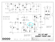
Here's one in an audio amplifier. Thanks to ZD2 and Q5, the MOSFET sees waaaay less than 60 volts from drain to source.
The input impedance of the MOSFET follower is extremely high, in fact it's higher than the output impedance of the cascoded current source (U1 + Q3). Thus the input stage operates at enormous gain:
Gain = gm_q2 * (rout_q3 //parallel_to// zin_q6)
The input impedance of the MOSFET follower is extremely high, in fact it's higher than the output impedance of the cascoded current source (U1 + Q3). Thus the input stage operates at enormous gain:
Gain = gm_q2 * (rout_q3 //parallel_to// zin_q6)
Attachments
I am re design a microphone preamplifier for ultra low noise. Eight in a 1U rack.
The challenge is not so about circuit noises, well known topics, but hum and noise from grounds.
This asks for differential circuits well balanced. Extreme common mode rejection. Low noise PSUs and PSRR. This I have acheived. Most runs from +15v 15v with about nothing tied to 0v analg ( virtual ) ground. PSU current is near constant.
Then I must add a LED peak level detector to indicate audio overload.
This is quite simple, basically a comparator ( LM393 ) to flash a red Led when audio level is more than +12 dBu rms.
This circuit is single ended, the issue is to not mess the analog ground. Mess from Led current that jumps 0mA / 4mA and Led control.
I try not to go all the way with separate ground and galvanic isolation with optocouplers.
Last edited:
Here's one in an audio amplifier.
Off topic: I see Mark is also into using real names as node names. I sometimes use names, sometimes the words from the aap noot Mies, even though it wasn't used anymore when I was at primary school.
https://nl.m.wikipedia.org/wiki/Leesplankje_van_Hoogeveen
It was a bit odd when I had to write in a report in English that a certain problem could be solved by adding some capacitance on node schapen.
Last edited:
Then I must add a LED peak level detector to indicate audio overload.
This is quite simple, basically a comparator ( LM393 ) to flash a red Led when audio level is more than +12 dBu rms.
This circuit is single ended, the issue is to not mess the analog ground.
I try not to go all the way with separate ground and galvanic isolation with optocouplers.
If you would have a suitable way to drive the LED in an optocoupler, you might as well drive a red LED with it instead of the infrared one in an optocoupler.
You could use some sort of shunt regulator to supply the clipping detector, or indeed not connect it to the ground.
Use a standard trick from the digital guys, specifically NPN emitter coupled logic:
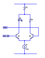
Leave the LED current source on all the time; never switch it off. Instead: steer the current. Either steer it to the LED, or steer it to a dummy load. Voila, the constant current remains constant, and nothing is injected onto the supplies or the grounds. I seem to recall Douglas Self doing something roughly similar in his Small Signal Audio Design book, in one of the last few chapters.
Here's one possible implementation. When the voltage at LED_ON is greater than the voltage at VREF, Q1 steers the constant current into the LED ("D1"). And when the voltage at LED_ON is less than the voltage at VREF, Q2 steers the constant current into dummy load resistor R1. As desired, the LED blinks on and off, but there is no noise injected into the supplies. Clearly the current in R2 is equal to the current in the CCS. So the top supply rail sees a constant, unchanging, current. Same as the bottom supply rail.
You probably noticed that R1 and R2 are completely optional; they are only included to make the drawing simple and symmetric. The circuit works equally well when R1=0 or R2=0 or both.
This sort of thing is done fairly frequently when the LED is a laser emitter and the constant current is hundreds of milliamps.
_
Attachments
My favorite mosfets for input differential pairs are ZVN3306A and ZVP3306A, both from Zetex/Diodes, Inc. The E-Line package is supposedly good for 1W dissipation, but I usually limit them to about 0.5W. One can always glue them to aluminum heatsink plates using a metal loaded epoxy like JB weld/ JB Kwik.
Last edited:
Then I must add a LED peak level detector to indicate audio overload.
This is quite simple, basically a comparator ( LM393 ) to flash a red Led when audio level is more than +12 dBu rms.
This circuit is single ended, the issue is to not mess the analog ground. Mess from Led current that jumps 0mA / 4mA and Led control.
The 393 must pull down to ground for a low output.
Should be able to use the 393 directly to illuminate the LED. (open collector). Set your clipping threshold on + input and apply signal on - input.
- Home
- Design & Build
- Parts
- Seeking a MOSFET