Here is the link to the new thread that is just for the XO. It has a zip file and explanations for the files in it.
https://www.diyaudio.com/community/threads/3-way-xo-help.415420/
I have removed the near field measurements as the far field measurements I gave earlier were already merged with the near field. ZIP file was triple checked to contain the right measurements.
https://www.diyaudio.com/community/threads/3-way-xo-help.415420/
I have removed the near field measurements as the far field measurements I gave earlier were already merged with the near field. ZIP file was triple checked to contain the right measurements.
Attachments
Note, he is showing vertical directivity not horizontal. So this would exist at differing listening heights, not off axis side to side in the roomI see that, that's not good. These will be listened to 90% of the time at 15 degrees off axis. Any way to fix this or is it just the nature of the drivers at the distance I have them apart?

Measuring on each axis produce more precise simulating. closer to the reality.The guide literally said I could take it at the same height for both of them.
Yes, it is normal and is appearing only in the vertical of-axis SPL - not to be confused with horizontal dispersion.is it just the nature of the drivers at the distance I have them apart?
Ok, now to figure out why when I load other's circuits in the program I am seeing a different response>Measuring on each axis produce more precise simulating. closer to the reality.
A4e. Any idea of why this might be? You seem to be the most experienced with the program.
Possibly with the options menu?
Attachments
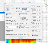
It's a notch filter, but it seems to have the side effect of adding a plateau to the low-pass filtering effect. To see what it does, apart from taming the big peak at 9kHz or so in the midrange's output, it, it is necessary to expand the amplitude axis.What is this thing? I haven't seen this form of filter before.
From the above, can we assume that the loudspeaker cabinet was placed on a stand such that it was located approximately in the middle of the gap between the floor and the ceiling? That is done to try and minimize the intensity of the first reflections.The tweeter and mid were taken right in the mid of each other per the guide at 670mm height from base of cabinet. The woofer was taken at it own height of 380mm
The measurement guide mentions: "Measure far field responses of woofer and mid-range driver and tweeter at 1000 mm in horizontal plane around the speaker." Was the microphone located at least 1000mm from the front of the baffle? In some circumstances, such as the loudspeaker system listening distances in the 2–3 meter range, a longer measuring distance can be used, such as 2000 mm. However, the signal levels would likely need to be increased to keep the signal-to-noise ratio as high as possible.
What local coordinate axis did you choose to be the loudspeaker's design axis? The design axis is typically chosen to be on the tweeter axis, as the tweeter is often the driver that is placed at ear height at the listening position.
For the most accurate simulation of the on-axis response, all measurements need to be taken relative to that design axis. That means keeping the microphone position fixed during measurements of the woofer, midrange, and tweeter. Doing so ensures that the correct time-of-flight to the measurement point is correctly included in each measurement, which shows up in the phase response. Get that wrong, and the filtered driver summations will be inaccurate. Note that the geometric driver offsets are also automatically considered, so the off-axis radiation behavior of each driver is 100% correctly included.
If each individual driver's on-axis measurement was to be used instead, this is likely not ideal. That's because each driver's radiation pattern would then need to be accurately modelled. Using a fixed design axis with a fixed measurement point avoids any attendant inaccuracies, as we are measuring the actual driver response. Each driver's intrinsic off-axis radiation characteristics are entirely included in its measurement.
Of course, it is possible to measure the response of each individual driver on its own axis. This then requires that the design point is quite far away from the baffle of the loudspeaker. This helps to ensure that the off-axis angle of each driver to the listening position is relatively small. This then allows the use of the driver's "on-axis" data in what is really an "off-axis" situation for any drivers that are not located on the design axis. For example, say we choose the tweeter axis to define the design axis. All drivers that are not coincident with the tweeter are now "off-axis" as far as their radiation patterns go when we are predicting their response at the target listening position at the design point.
Last edited:
- Home
- Loudspeakers
- Multi-Way
- Saggy Bandpass filter