D
Deleted member 375592
Even the best loudspeakers sound quite poorly in nowadays squeezing living rooms. The problem of room reverberation can be addressed by extensive soundproofing and/or by using very directional loudspeakers - but covering the walls and ceiling with class A acoustic foam is not cheap & utterly destructive to the peace in the family; commercial controlled directivity loudspeakers cost a fortune while developing your own without an anechoic chamber nearby is unrealistic. However, in some situations it is possible to use the room geometry to reduce room reverberation and improve the listening conditions.
where C2F is ceiling-to-floor (typically 9’, ignoring 1’ of ceiling space for pipes, etc) height, NS is the number of drivers, and H is the ear height for a sitting listener (typically 2’8” … 3’). Drivers shall be focused (arched and angled, as per near-field beamforming) onto the DIYer and his ever-grateful family at 9’…11’. In (a simplified) theory, such array shall have wide horizontal dispersion and its impulse response (on the axis) shall look like

with floor and ceiling reflections interleaving, each having a small (~1/NS) relative amplitude, with loudness decaying as (1/sqrt(distance)), contrary to (1/distance) for point source loudspeakers. However, I could not find any published (by others) real-world measurements, to either confirm or disprove this theory. Thus, I measured what I could myself. Of course, the results are specific to the room & drivers – but something, even little, is better than nothing.
The drivers are Dayton Audio Sig150-4 mounted in approx. 3.6L boxes angled 60⁰ inwards, which boxes are mounted on a long plank which is mounted into the corner of a somewhat spartan room 25’ x 14’ x 9’. Multiple drivers were connected in series.


The amplifier output was set to get 80 dB SPL @1m from a single driver. A (pre & post) calibrated 12 dBA cardio microphone on 2i2 Gen 3 USB audio interface was used. Room Impulse Responses (RIR) were obtained by a regularized Exponential Sine Wave (ESS) method Loudspeakers for AEC: Measurement and Linearization - File Exchange - MATLAB Central (mathworks.com) (to be updated).
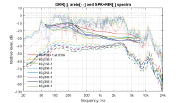
The RIRs were postprocessed to extract the Direct to Reverberant Ratio (DRR(f)) as the Y-value that the polynomial approximation of the corresponding normalized reverberant slope(f) crosses at X=0:

Obviously, speakers’ arraying does not affect RT60(f).
Measurement distances are 100:50:400 cm, with 300cm as target. The default measurement height is 85cm, to be varied 70:5:100cm. The first 20ms of RIR, DRR, arete (top of the ridge) of wavelet-transformed RIR, and total FR are considered to be more important than other metrics.


At target distance & nominal ear height. See the details below.


Red lines are for quasi-anechoic conditions (alas, wrong polarity).


Variations of Listener’s Ear Height
3 Drivers
Variations of Listener’s Distance
Variations of Listener’s Ear Height
6 drivers, straight line [e] vs angled only [f] vs arched only vs arched and angled [j]


As usual, [h] stands for a single driver as baseline.
TBD
[1] Disclaimer: The objective measurements below are somewhat related to but do not characterize human auditory perception to any highly disputable degree of fullness or precision.
Introduction
Let’s consider an alternative as sparse (3…6 drivers) speaker arrays positioned in the room corners so that the floor & ceiling of a typical room create a tall virtual column. The driver’s height is defined bygap=(C2F-H)/NS; aH=(0:NS-1)'; aH=aH*gap+gap/2;
where C2F is ceiling-to-floor (typically 9’, ignoring 1’ of ceiling space for pipes, etc) height, NS is the number of drivers, and H is the ear height for a sitting listener (typically 2’8” … 3’). Drivers shall be focused (arched and angled, as per near-field beamforming) onto the DIYer and his ever-grateful family at 9’…11’. In (a simplified) theory, such array shall have wide horizontal dispersion and its impulse response (on the axis) shall look like
with floor and ceiling reflections interleaving, each having a small (~1/NS) relative amplitude, with loudness decaying as (1/sqrt(distance)), contrary to (1/distance) for point source loudspeakers. However, I could not find any published (by others) real-world measurements, to either confirm or disprove this theory. Thus, I measured what I could myself. Of course, the results are specific to the room & drivers – but something, even little, is better than nothing.
Methods[1]
This design and measurements are concentrated on midrange applications, 300Hz – 3kHz, of the maximal sensitivity of human ear to the Direction of Arrival (DoA).The drivers are Dayton Audio Sig150-4 mounted in approx. 3.6L boxes angled 60⁰ inwards, which boxes are mounted on a long plank which is mounted into the corner of a somewhat spartan room 25’ x 14’ x 9’. Multiple drivers were connected in series.
The amplifier output was set to get 80 dB SPL @1m from a single driver. A (pre & post) calibrated 12 dBA cardio microphone on 2i2 Gen 3 USB audio interface was used. Room Impulse Responses (RIR) were obtained by a regularized Exponential Sine Wave (ESS) method Loudspeakers for AEC: Measurement and Linearization - File Exchange - MATLAB Central (mathworks.com) (to be updated).
The RIRs were postprocessed to extract the Direct to Reverberant Ratio (DRR(f)) as the Y-value that the polynomial approximation of the corresponding normalized reverberant slope(f) crosses at X=0:
Obviously, speakers’ arraying does not affect RT60(f).
Measurement distances are 100:50:400 cm, with 300cm as target. The default measurement height is 85cm, to be varied 70:5:100cm. The first 20ms of RIR, DRR, arete (top of the ridge) of wavelet-transformed RIR, and total FR are considered to be more important than other metrics.
Results
number of drivers [h->1, n->3, m->4, n->5, j->6] summary
At target distance & nominal ear height. See the details below.
Single Driver
Red lines are for quasi-anechoic conditions (alas, wrong polarity).
6 drivers
Variations of Listener’s Distance
Here and below, red lines are of a single driver at 300cm, as the reference.Variations of Listener’s Ear Height
5 drivers
Variations of Listener’s Distance
Variations of Listener’s Ear Height
4 drivers
Variations of Listener’s Distance
...oops, only 20 imagesVariations of Listener’s Ear Height
3 Drivers
Variations of Listener’s Distance
Variations of Listener’s Ear Height
6 drivers, straight line [e] vs angled only [f] vs arched only vs arched and angled [j]
As usual, [h] stands for a single driver as baseline.
Other Observations
- The measurements show only 10 dB of improvements in DRR but subjective perceptual improvement is much stronger, far beyond expected.
- Due to 15.5 dB lower SPL at each driver, non-linear distortions and Barkenhouse noise are proportionately lower.
- The dynamic range widens, high SPL are not distorted.
- The (1/sqrt(distance)) effect is realized only partially per measurements but nearly fully by perception.
- Judging by ear at 10’, 6 drivers with 90dB SPL @ 2.83V sensitivity are louder than a 110 dB SPL single driver, ~same Z.
Discussions
Many more drivers & configurations were built and measured in the last year. None of them contradicts the data above, and these have relatively low additional meaningful information and were omitted to avoid overloading readers.TBD
Conclusions
- Sparse speaker arrays are a compromise. Particularly, they are not a good fit if you require that listening experience shall be invariant to ear’s height. Left/right/closer/farther are not a problem.
- You do not need 20 drivers / column to realize line source advantages.
- You do not need near-perfect expensive midrange drivers to get decent sound.
- You do not need 400W amplifiers, for sure. Even 100W is too much.
- An average DIYer can build a sparse speaker array and adjust it to his preferences without getting into much expense or serious technical difficulties.
[1] Disclaimer: The objective measurements below are somewhat related to but do not characterize human auditory perception to any highly disputable degree of fullness or precision.
Attachments


From a production and engineering perspective, content is mixed/mastered for point source behavior and in such, near and mid field listening to line source devices is deeply flawed. Depending on the full design behavior of the array….MAYBE…..the prescribed effective listening distance is 7x the length of the line…..typically it’s closer to 10x. Our ear/brain mechanism used target frequencies to identify height and distance…..evolutionary developments for hunting, communication and self defense. These spacial cues are synthesized by the engineer from a stereo point source using phase, time and relative distance. A line source completely obliterates the initial objective and as such, IMO serves little purpose for stereo listening in a closed space. No matter the efforts of a line source designer, the constraints of a closed space can never be eliminated to the point of anechoic behavior….the only chance where a line may be perceived as a point is by effectively eliminating the ‘point’ of reference…….outside and far field defined above as 7-10x the length of the line.
I did some extensive work last year with 5 element Bessel arrays last year using full range drivers in an attempt to overcomes the inherent challenges of point source and line source behavior. I haven’t published anything yet as the Bessel array introduced unexpected challenges…….a mid field directivity perception that’s hard to describe……and odd sense of location when operated in stereo…….all the monopole testing prior went right out the window. There’s potential here though and for let’s say center channel use in a home theater environment?……I’ve personally concluded the horizontal Bessel array is the best alignment possible with current transducer technology.
I did some extensive work last year with 5 element Bessel arrays last year using full range drivers in an attempt to overcomes the inherent challenges of point source and line source behavior. I haven’t published anything yet as the Bessel array introduced unexpected challenges…….a mid field directivity perception that’s hard to describe……and odd sense of location when operated in stereo…….all the monopole testing prior went right out the window. There’s potential here though and for let’s say center channel use in a home theater environment?……I’ve personally concluded the horizontal Bessel array is the best alignment possible with current transducer technology.
Last edited:
D
Deleted member 375592
"A line source completely obliterates the initial objective and as such, IMO serves little purpose for stereo listening in a closed space"
That's what I thought too a few years ago but my listening experience says otherwise. Alas, at this point in time, I can't explain it any better than I just did. I agree that my explanations are not convincing much, if any.
That's what I thought too a few years ago but my listening experience says otherwise. Alas, at this point in time, I can't explain it any better than I just did. I agree that my explanations are not convincing much, if any.
That's not to say that it can't sound pleasing to a listener......clean headroom with dynamic range and consistent directivity goes a long way.......it's the imaging that can't recall what the mix/mastering engineer intended.
D
Deleted member 375592
For me, it all started with a question - what is cheaper: to treat the room properly or invest in additional drivers? IMHO, line source is better than a point source in an untreated room. I think that L/R imaging is fairly preserved (I've been comparing it to reference Focal spks). I listen mostly to classical and prefer live unedited recordings, so I don't care much about "intentions". In my case, the ability to hear the performers distinctively and clearly dominates.
It may be very different (up to opposite) for others, of course.
It may be very different (up to opposite) for others, of course.
Last edited by a moderator:
... but in a 2 mic stereo recording... how about that.. there is no mix or mastering... what the natural state of things?mix/mastering engineer intended.
//
@mikets42 thanks for sharing all this data and for doing all the work. Great job! I have built a 24-driver line array using the TC9 drivers and did many measurements that are available online. I totally agree with your conclusions here. Speaker Dave (RIP) had done some of this work and there are papers in the AES library on it. I am too lazy to find them, but I wanted you to know that there are others who went down this path and successfully designed commercial speakers based on theory. Check the Snell XA Reference design.
https://www.stereophile.com/content/snell-acoustics-xa-reference-tower-loudspeaker-measurements
The main theory is that the line length can be shortened to where it matches the frequency to which vertical pattern control is desired. For example, a tweeter array that wants vertical pattern control to 1 kHz need only be 1.2 ft long. This is the rationale behind the expanding array. I started to build this in my old house but then gave up:
https://www.diyaudio.com/community/threads/corner-expanding-line-array-with-kef-q100.258246/
Everything by Mapleshade Records?a recording that is 2 mic direct to disk or tape
https://shop.mapleshadestore.com/Recordings_c_11.html
"all recorded live to 2-track analog tape with no EQ, no overdubs, no filtering, no compression, or other studio cosmetics."
There is plenty of mozart recordings by tel arc ( and teldec) which use two mics, preamp and no procesing, just adc and recording machine.Please reference such a recording that is 2 mic direct to disk or tape please.
Attachments
Comprehension is important……I have a 961 in storage…..it DOES have very colorful pres and EQ as well as pan in each channel strip…….not sure what they’re trying to say in this statement beyond more audiophoolery.There is plenty of mozart recordings by tel arc ( and teldec) which use two mics, preamp and no procesing, just adc and recording machine.
Are the little white switches above the blue knobs bypass switches for the tone control? If so, they probably mean those were in bypass.
https://reverb.com/item/46686738-studer-961-10-2-analog-mixing-console
https://reverb.com/item/46686738-studer-961-10-2-analog-mixing-console
D
Deleted member 375592
There were and still are ongoing religious battles in the recording communities around DG's simple XY vs. multi-mic with obnoxious digital processing. Some companies (like Channel Classics) are prized for recording direct-on-DSD. There are re-issues of master tapes such as Living Stereo, etc.
It all depends on the music you listen to. If you are into HIPP baroque, unedited live recordings are 90% of your (SA)CDs.
It all depends on the music you listen to. If you are into HIPP baroque, unedited live recordings are 90% of your (SA)CDs.
From a production and engineering perspective, content is mixed/mastered for point source behavior and in such, near and mid field listening to line source devices is deeply flawed.
Based on the same line of reasoning, mastered recordings should preferably be listened to over the exact same equipment as was used during mastering, in an environment that is acoustically as similar to the place where mastering was done as possible and at the same volume. The DIY part then becomes DIY construction work, to make a room as similar as possible to the place where mastering was done.
To a degree….yes…..you’re correct. Mastering labs typically don‘t have extreme acoustic treatment and most are mid field environments. Speakers on the other hand…..that varies significantly to the preference of the engineer. My experience has been most are three way systems.
D
Deleted member 375592
While trying to match a single tweeter with a focused midrange speaker array, I ran into a problem: the response of the speaker array does not depend on distance in the range of 2...4m, while the tweeter falls as 1/R. Then I looked into a 20cm ribbon midrange/tweeter. It had a large bump at high frequencies (15kHz or so). To flatten it, I tried a prefilter (LP IIR at 3500Hz, 1st order) and an acoustic post filter (simply a layer of acoustic foam over the ribbon's surface.
FR is roughly the same.
The results were quite surprising: the acoustic filter lowers distortions. Here are 2nd and 3rd harmonics:


Here 80-v2 (red) is the original AMT920, 80-v2-lpf3500-lpn1 (yellow) is prefiltered digitally, 80-v4 (green) is postfiltered acoustically.
I am utterly puzzled and not sure if I shall believe my eyes. Have you seen anything like that?
FR is roughly the same.
The results were quite surprising: the acoustic filter lowers distortions. Here are 2nd and 3rd harmonics:
Here 80-v2 (red) is the original AMT920, 80-v2-lpf3500-lpn1 (yellow) is prefiltered digitally, 80-v4 (green) is postfiltered acoustically.
I am utterly puzzled and not sure if I shall believe my eyes. Have you seen anything like that?
Hi, yeah makes sense at least with simple reasoning: as your acoustic damping material has static properties like thickness, it's more effective the shorter the wavelength. The harmonics have shorter wavelength than the fundamental, so they are attenuated more.
- Home
- Loudspeakers
- Multi-Way
- On sparse speaker arrays