I am trying to make a power supply for a microphone preamp.
I have a transformer with a 12V AC winding and I would like to obtain 48V for phantom power and something around 12V to power relays, LEDs and a vu meter buffer.
The first approach I tried uses a voltage multiplier which produces effectively the desired 48V, and a bog standard 7812 section for the other rail.
The two circuits work well independently, but not if they are connected together to the same transformer winding.
It looks like the diodes in the multiplier and the ones in the bridge rectifier are interacting between each other creating some undesired current paths.
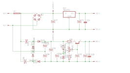
I have tried another circuit borrowed from a JLM power supply and in this case the two sections work well together (I guess it's because C1 and C2 provide isolation between the two rectifier sections) however despite the schematic claiming you can get 48V from a 15V AC transformer winding, my transformer which in fact outputs 14.5V AC (it's rated at 1A so the voltage is increased with no load) can only produce max 36V DC on the output.
I am looking for any suggestions on how to modify any of these two versions to meet my requirements, or by all means if you have an alternative circuit to suggest for this application.
I have a transformer with a 12V AC winding and I would like to obtain 48V for phantom power and something around 12V to power relays, LEDs and a vu meter buffer.
The first approach I tried uses a voltage multiplier which produces effectively the desired 48V, and a bog standard 7812 section for the other rail.
The two circuits work well independently, but not if they are connected together to the same transformer winding.
It looks like the diodes in the multiplier and the ones in the bridge rectifier are interacting between each other creating some undesired current paths.
I have tried another circuit borrowed from a JLM power supply and in this case the two sections work well together (I guess it's because C1 and C2 provide isolation between the two rectifier sections) however despite the schematic claiming you can get 48V from a 15V AC transformer winding, my transformer which in fact outputs 14.5V AC (it's rated at 1A so the voltage is increased with no load) can only produce max 36V DC on the output.
I am looking for any suggestions on how to modify any of these two versions to meet my requirements, or by all means if you have an alternative circuit to suggest for this application.
Attachments

https://www.ebay.com/itm/201651778075
https://www.aliexpress.com/item/1005005396072901.html
DC-DC SMPS booster + output filter to get rid of noise. Connect the DC-DC booster to a 12VDC stabilized voltage or make another diode bridge and CRC filter and feed it with raw DC. Of course, buy a model that has a 48VDC output from 12VDC input and a RF filter operating at 50V or more. You can also replace the electrolytes in the filter with a 63V ones.
Last edited:
I have tried this, it appears the voltage across C17 is not stable but slowly climbs from 20V upwardsJust a thought - not sure wether it is actally that good ...
I am a bit concerned about potential noise with using a cheap SMPS section, even if the supply line can be well filtered I reckon there could be some EMI radiated in the enclosure which can be easily picked up by the sensitive microphone level circuitDC-DC SMPS booster + output filter to get rid of noise. Connect the DC-DC booster to a 12VDC stabilized voltage or make another diode bridge and CRC filter and feed it with raw DC. Of course, buy a model that has a 48VDC output from 12VDC input and a RF filter operating at 50V or more. You can also replace the electrolytes in the filter with a 63V ones.
Yes, and it depends very much on capacities. Simulate for at least 10-20 s!but slowly climbs
I have left it on for about 15 minutes and the voltage went from 20V to 30V and still climbing up
Voltage multiplier is a "soft" thing with a lot of ripple. That ripple is not easy to remove, especially with this simple regulator provided. According to your schematic, I don't think both power branches can be grounded together, and that these problems originate from there.I am a bit concerned about potential noise with using a cheap SMPS section, even if the supply line can be well filtered I reckon there could be some EMI radiated in the enclosure which can be easily picked up by the sensitive microphone level circuit
A better version is the DC-DC converter and filter. Or a separate transformer, which would be the best solution. When working with sensitive circuits, transformers must be magnetically shielded or separated sufficiently. It is preferable to use toroidal transformers due to less radiation.
Last edited:

no load
no load, that would be the situation where the connected relays are powered offOh, so you have actually built it!
Is there any load attached?
You could include a 10-100k resistor as minimum constant load?no load
With a 100k load the voltage is stable about 19V , but I cannot reference both rails to chassis, in which case it goes up to 34 V
I think for the phantom power rail it is mandatory to have it referenced to chassis for low noise, but perhaps the relay power rail it's ok to leave that floating ?
I think for the phantom power rail it is mandatory to have it referenced to chassis for low noise, but perhaps the relay power rail it's ok to leave that floating ?
Try to increase the value of the capacitors in the multiplier. I don't know what values you have now?
The problem is certainly solvable using the right configuration of voltage multiplier, but you should provide a schematic showing explicitly the connection(s) between the two supplies, otherwise any proposition will be a stab in the dark, with unsatisfactory results most likely
- Home
- Amplifiers
- Power Supplies
- DC 12V and 48V from a single 12V AC transformer winding