I still wont throw it...
Fast forward 1 hour...
A 10uF ceramic capacitor is now in series to the 1K resistor. The circuit now works! but...
There is a bit too much distortion. Maybe because i didnt add the other components. I Also added 47nF + 10R in series at the output and the circuit consumes much less power now. The transistors dont heat up as much anymore.
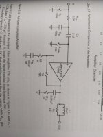
I now found image 3.16.
So THOOOSE are the components that i need to add to make it work properly, i guess. But where i could find a 100 uF non polar capacitor!? Those are not easy to find. The only thing i could do is to use 22uF x5 in parallel (25V, ceramic, SMD).
So if i add those components it should work with LOW (almost unhearable) distortion, hopefully.
I Also have to Mount the C3505 to the heatsink since its used as some sort of thermal compensation...
Fast forward 1 hour...
A 10uF ceramic capacitor is now in series to the 1K resistor. The circuit now works! but...
There is a bit too much distortion. Maybe because i didnt add the other components. I Also added 47nF + 10R in series at the output and the circuit consumes much less power now. The transistors dont heat up as much anymore.
I now found image 3.16.
So THOOOSE are the components that i need to add to make it work properly, i guess. But where i could find a 100 uF non polar capacitor!? Those are not easy to find. The only thing i could do is to use 22uF x5 in parallel (25V, ceramic, SMD).
So if i add those components it should work with LOW (almost unhearable) distortion, hopefully.
I Also have to Mount the C3505 to the heatsink since its used as some sort of thermal compensation...
Attachments
Keep reading. Learn about calculating input filter and feedback filters. You won't need a 100uF blocker cap, actual value will be much lower. 19k bias resistor is actually a pretty low value. Might be hard to drive. 47k is more common but your feedback values should match.
Also its written that Cc should be as high quality as possible like polypropilene. But all i have is ceramic, so for now i will use a ceramic one. It should not affect performance too much.
I'm testing the circuit with just ±14V for now.
If i see that it improves by adding the other components i will try to test it at high power at ±35 or maybe even ±40V to get a bit more power.
The transistors are now mounted on a CPU cooler! I will always keep the fan on.
I'm testing the circuit with just ±14V for now.
If i see that it improves by adding the other components i will try to test it at high power at ±35 or maybe even ±40V to get a bit more power.
The transistors are now mounted on a CPU cooler! I will always keep the fan on.
https://www.reichelt.com/fi/en/visa...apacitor-100-f-63-vdc-vis-elko-5388-p962.htmlBut where i could find a 100 uF non polar capacitor!? Those are not easy to find
https://eu.mouser.com/ProductDetail/Nichicon/UES1V101MPM1TD?qs=WJSLByB5Mu3E8mTj7sTGqg==But where i could find a 100 uF non polar capacitor!?
don´t get too dissapointed, if you manage to do some listening. Ceramic´s are the absolute worst related to sound quality.But all i have is ceramic, so for now i will use a ceramic one. It should not affect performance too much.
But excellent decoupling cap´s when fighting high freq. and oscillations. In the signal path, everything else is better than ceramic´s 😉
Thank you for the links, but i settled with ceramic caps because they have a much longer Lifetime (and i have them already).
Initially i didnt think about paralleling multiple caps to get to 100uF.
Initially i didnt think about paralleling multiple caps to get to 100uF.
I actually have some polypropilene ones but they are 1uF. I have to parallel once again.don´t get too dissapointed, if you manage to do some listening. Ceramic´s are the absolute worst related to sound quality.
But excellent decoupling cap´s when fighting high freq. and oscillations. In the signal path, everything else is better than ceramic´s 😉

That´s fine when you´re experimenting.I actually have some polypropilene ones but they are 1uF. I have to parallel once again.
When doing the final build/layout, buy the proper value/size parts 😉
Where was that written?Also its written that Cc should be as high quality as possible like polypropilene.
It possible to use a 5mm lead length Wima or equiv but you want to stay away from the longer lead spacings.
On the BC-1 design that I did with Bob Cordell, Cc (miller compensation cap) was specified as a 200V NPO/COG leaded MLCC (Multi-layer Ceramic cap)
I use Kemets from Mouser but there are others as well
For the BP ecap, we used Nichicon UES (green)
In Denmark, we call this "Ordkløveri".distiguish 🤣 🤣 🤣 🤣 🤣 try distinguish
In Norway, they call it "flisepikk"
Try Google translate, and you´ll get my drift 🤣 🤣 🤣 🤣
Trying to correct others, you could at least have done YOUR spelling right 🤣 🤣 🤣 🤣
Last edited:
COG/NPO are actually excellent for in the signal path. X7R are better for decoupling. Non polar electrolytics are fine for larger values, like the DC blocker for feedback.Forgot......
But you have to distinguise, which part is for what. Cog´s/ceramic are fine for decoupling.
NOT in signal path.
I think it's also prudent to have a big non-polarized electrolytic (e.g. 220uf @ 50V) between R3 and ground.
Let´s just agree on disagreeing 👍COG/NPO are actually excellent for in the signal path. X7R are better for decoupling. Non polar electrolytics are fine for larger values, like the DC blocker for feedback.
I'm still having problems. Even after adding all the filters. All capacitors i used are polypropilene including the one that should be 100uF (I used 10uF but polypropilene).
The output power is very low and the distorsion is high, nowhere near to what it should be. I guess there is nothing else to do anymore, its probably a bad PCB layout or i need too premium components that are super expensive or i have to wait more than 1 month to get by also wasting €30 for shipping.
Well, it was a good run, but unfortunately thats where it ends, i guess...
Its much less expensive buying a pre built class D amplifier even if it has a higher distortion. Just use it at a lower power to significantly reduce distortion. A 300W x2 amplifier can be used as a 200 - 175W x2 and the distortion will be greately reduced.
Last edited:
- Home
- Amplifiers
- Solid State
- Problem with dual supply amplifier (triple emitter follower)