This is my first post, so any advice, including "Go search better in the forum," is accepted.
I need a simple phono preamp to upgrade a Philips home system made in mid '70s. It has a cheap vinyl record player on top with a crystal pickup, and I decided to replace it with one from the same era having an MM pickup instead. It's nothing fancy, but I need a working preamp for a pretty average system. I have found this old thread here, where this design was suggested:

The construction seems to be straightforward. However, as I will need a double rail power supply, I will have to add another transformer because the original system (while also using op-amps) does not have two rails but just a single 15V supply. The tread included the suggestion to change the design for a single supply:

I first modeled the schematic in LTSpice, and the result of the simulation was OK. Then, I implemented the design in hardware, and it did not work. Interestingly, when I replaced the op amp with LM386, it kind of worked, but with one of the chips. The other, very identical chip from the same batch did not work. All the op amps I have tried are functional. One of the problems that I have found is the 330uF capacitor charging slowly, as there is a significant potential difference between the ground and the inverted input in the modified version. The original schematic does not imply the significant static difference in the potential between the signal ground and the inverted input, so the problem should not have happened there. As the current through the capacitor is rather small, the potential at its positive terminal stays low for a long time, significantly lower than that of the non-inverted input. This may be the main reason why the opamp does not work.
So I need advice on how the design could be modified to make it work properly from a single rail supply.
I need a simple phono preamp to upgrade a Philips home system made in mid '70s. It has a cheap vinyl record player on top with a crystal pickup, and I decided to replace it with one from the same era having an MM pickup instead. It's nothing fancy, but I need a working preamp for a pretty average system. I have found this old thread here, where this design was suggested:
The construction seems to be straightforward. However, as I will need a double rail power supply, I will have to add another transformer because the original system (while also using op-amps) does not have two rails but just a single 15V supply. The tread included the suggestion to change the design for a single supply:
I first modeled the schematic in LTSpice, and the result of the simulation was OK. Then, I implemented the design in hardware, and it did not work. Interestingly, when I replaced the op amp with LM386, it kind of worked, but with one of the chips. The other, very identical chip from the same batch did not work. All the op amps I have tried are functional. One of the problems that I have found is the 330uF capacitor charging slowly, as there is a significant potential difference between the ground and the inverted input in the modified version. The original schematic does not imply the significant static difference in the potential between the signal ground and the inverted input, so the problem should not have happened there. As the current through the capacitor is rather small, the potential at its positive terminal stays low for a long time, significantly lower than that of the non-inverted input. This may be the main reason why the opamp does not work.
So I need advice on how the design could be modified to make it work properly from a single rail supply.
Use a 25V capacitor.
The 330uF capacitor's leakage current may be too high for the circuit to work. You can reduce the value of the capacitor by several times before the bass response is affected.
Ed
The 330uF capacitor's leakage current may be too high for the circuit to work. You can reduce the value of the capacitor by several times before the bass response is affected.
Ed
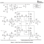
An TI appnote sloa042 shows one solution for opamps in a single-supply preamp. IMO, single supply design is complicated and should be 24vdc or more. There is an opamp to buffer the midpoint resistors. A TLE2426 is lifebuy but might be still available for simplicity and low impedance.
Attachments
Crystal pickup requires a high input impedance ! The shown circuit may not be useful at all !It has a cheap vinyl record player on top with a crystal pickup, and I decided to replace it with one from the same era having an MM pickup instead.
Change C3 to 22 uF, 63 V. The loss in bass will be very small.
You could actually blow up the capacitor with the present circuit, as it is rated for 6.3 V and should settle to 7.5 V.
I suggested 63 V working voltage because 63 V electrolytics usually have a somewhat better tan(delta) than 10 V or 16 V types. Anything well above 7.5 V should work.
You could actually blow up the capacitor with the present circuit, as it is rated for 6.3 V and should settle to 7.5 V.
I suggested 63 V working voltage because 63 V electrolytics usually have a somewhat better tan(delta) than 10 V or 16 V types. Anything well above 7.5 V should work.
Could you please read the sentence you quoted?Crystal pickup requires a high input impedance ! The shown circuit may not be useful at all !

Indeed, I waited for a few minutes, and the voltage on the inverting input gradually got to almost the same level as non-inverting, and then the output signal showed up. The time constant for charging the 330uF capacitor through a series resistor of some 600K from a high voltage at the output is pretty high, roughly 3 minutes. Even if I use a 22 uF, it's still above 10 sec so that it will mimic a vacuum tube preamp very successfully. Another trouble is that the schematic will be very sensitive to the capacitor leakage. If, at some time, it starts leaking more, the voltage on the capacitor will gradually drop and, at some point, will send the output of the opamp to high again. I am gradually convincing myself to put a separate transformer for the preamp to avoid all the problems. I was thinking about any other solution that would either charge the capacitor faster or isolate it somehow from the ground, but I didn't come to any reasonable conclusion.Change C3 to 22 uF, 63 V. The loss in bass will be very small.
You could actually blow up the capacitor with the present circuit, as it is rated for 6.3 V and should settle to 7.5 V.
I suggested 63 V working voltage because 63 V electrolytics usually have a somewhat better tan(delta) than 10 V or 16 V types. Anything well above 7.5 V should work.
Thanks to everybody for your help.
Theoretically, with 22 uF, it should take 9.27 seconds with a rail-to-rail op-amp and a bit longer with a non-rail-to-rail op-amp until the output starts going down. After that, it settles with a 22 ms time constant.
In practice, a decent quality electrolytic capacitor leaks a lot when it hasn't been used for a very long time. The leakage current then gradually drops when you apply voltage to it. If you use it once a year or more, the leakage stays low.
In practice, a decent quality electrolytic capacitor leaks a lot when it hasn't been used for a very long time. The leakage current then gradually drops when you apply voltage to it. If you use it once a year or more, the leakage stays low.
@MarcelvdG, thank you.
I haven't tried the rail-to-rail supply yet. However, when I think about it, I don't really see why, if the signal ground is not tied to any of the rails, the C3 capacitor has to charge to any potential. The output is galvanically connected to the inverted input through the resistors, and the non-inverted input is again galvanically connected to the signal ground through the pickup and R1. So, to equalize the inputs, the output should get to the level of the signal ground very fast, which means that the potentials on both ends of C3 will equalize, and it will only have a variable charge component to it. It will work alongside R1 to boost the low frequencies. C3 may see some potential difference only after the power is supplied before things settle or if the balance between the rails is not kept. Correct me if I am wrong.
I haven't tried the rail-to-rail supply yet. However, when I think about it, I don't really see why, if the signal ground is not tied to any of the rails, the C3 capacitor has to charge to any potential. The output is galvanically connected to the inverted input through the resistors, and the non-inverted input is again galvanically connected to the signal ground through the pickup and R1. So, to equalize the inputs, the output should get to the level of the signal ground very fast, which means that the potentials on both ends of C3 will equalize, and it will only have a variable charge component to it. It will work alongside R1 to boost the low frequencies. C3 may see some potential difference only after the power is supplied before things settle or if the balance between the rails is not kept. Correct me if I am wrong.
I assume we are discussing the second schematic of post #1 and that there is a cartridge connected to the input. When the supply goes from 0 to 15 V at start up, the voltage divider consisting of two 100 kohm resistors will charge the 1 uF input coupling capacitor until it reaches one half of 15 V. The time constant is about 50 ms, so this happens fairly quickly.
The op-amp will try to also bring its negative input to 7.5 V, but can only do that by charging C3, which takes some time - almost 150 seconds with 330 uF and almost 10 seconds with 22 uF if the op-amp output can go all the way to the positive rail, somewhat longer if it can't.
I don't know what exactly happens when you use an LM386 instead of an op-amp. It has internal 50 kohm resistors from its inputs to ground and an internal feedback network, so it will not work as intended by the designer.
You are absolutely right; that's exactly what I experienced. I was comparing that behavior to the original schematic (the first one in the post), with a rail-to-rail supply, and that should work well with TL072. This discussion makes me think that the original schematic can't be redesigned to work with one rail supply. So I will probably stick to the original design and use a separate transformer. Thank you!
You can make a negative rail from the existing transformer by using a voltage doubler. See figure 2 and reverse the polarity of the diodes. The return current will flow through the existing diode bridge. This is okay since only a few milliamps are needed. The split supply should have zener diode regulators.
Ed
Ed
I only now see that the supply is 19 V rather than 15 V, so half of it is 9.5 V. It doesn't change the times, only the required capacitor working voltage.
Is it a clean 19 V? If not, you inject supply ripple into the input via the upper 100 kohm resistor.
Is it a clean 19 V? If not, you inject supply ripple into the input via the upper 100 kohm resistor.
For single supply, maybe a simple vintage discrete circuit would be suitable:
http://www.douglas-self.com/ampins/discrete/2Q-RIAA/2Q-RIAA.htm

http://www.douglas-self.com/ampins/discrete/2Q-RIAA/2Q-RIAA.htm
Thank you! I have a 12 V transformer that will produce 17V dc, and the opamp works perfectly well with 8V between ground and the rails. So I’ll probably just use two Zeners with resistors in series to establish a virtual ground.You can make a negative rail from the existing transformer by using a voltage doubler. See figure 2 and reverse the polarity of the diodes. The return current will flow through the existing diode bridge. This is okay since only a few milliamps are needed. The split supply should have zener diode regulators.
Ed
In case anyone is interested in the design method of the circuit of post #16, I started a thread about it: https://www.diyaudio.com/community/...rworth-high-pass-included.413649/post-7704134
Oh, I was not getting the point. Indeed, I can use the existing power supply from the device and add a negative rail to it by using a voltage doubler, and that will eliminate the need for a separate transformer, with two identical Zeners to balance the rails. That makes perfect sense.Thank you! I have a 12 V transformer that will produce 17V dc, and the opamp works perfectly well with 8V between ground and the rails. So I’ll probably just use two Zeners with resistors in series to establish a virtual ground.
- Home
- Source & Line
- Analogue Source
- Advice on single rail supply phono preamp design