I agree, for the resistor with 5 color bands as you show in your photo - that is 68R.

Identifying that chip may prove to be difficult!
I currently can’t see any marking under the dried adhesive

I currently can’t see any marking under the dried adhesive
That is not good news Andy - are you sure there are no markings on the side of the can, clearly there is nothing on the top. Lets hope the IC is still OK.
LM723 maybe? https://www.ti.com/product/LM723#pps It is well-known and it comes in a 10-pin TO-100 package.
(Contrary to what the link says, the LM723 is most certainly not an LDO, just a series regulator.)
(Contrary to what the link says, the LM723 is most certainly not an LDO, just a series regulator.)
I’ve carefully scraped some of the dried adhesive off and still can’t see anything , I think I’ll have to remove it to get a closer look.That is not good news Andy - are you sure there are no markings on the side of the can, clearly there is nothing on the top. Lets hope the IC is still OK.
The components surrounding it do have black smoke like marks on them 😩
Found this on a German site. Might prove useful?
LInk to the thread via Google Translate is HERE
Note that there's a full schematic that the poster drew up and he says if anyone would like the full schematic in detail to PM him.
LInk to the thread via Google Translate is HERE
Note that there's a full schematic that the poster drew up and he says if anyone would like the full schematic in detail to PM him.
Attachments
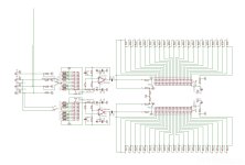
That schematic does not show any details on the PSU, however it does show a +/- 15VDC supply for the op amp. So my guess is the PSU IC is a dual +/- 15 volt DC regulator in a 10 pin metal can IC.
The ones in the photo in post #20 are 68 ohm. Do the burnt ones measure open circuit?
The ones in the photo in post #20 are 68 ohm. Do the burnt ones measure open circuit?
I am guessing that the IC is an LM325H dual tracking +/- DC voltage regulator, interesting that the resistors are still measuring OK, so they are seeing heavy current. The IC is overload and current limit protected, so maybe faulty tantalums - that would not be the first time.
If the IC is faulty, it is obsolete so apart from a China copy, I do not know where you might get an original TI or NS device.
If the IC is faulty, it is obsolete so apart from a China copy, I do not know where you might get an original TI or NS device.
Last edited:
LM325 indeed makes more sense than the LM723 I suggested. As a check, you can try to trace out the circuitry around it and see if it matches what is in the LM325 datasheet (if the tantalum capacitors are not the issue).
If they are Tantalum capacitors, one leg must be marked with a + symbol - is that sown next to one of the legs - otherwise they could be ceramic capacitors.Does K1 on a tantalum capacitor equate to 1uf ?
If the IC is an LM325, then the datasheet for that IC shows 1uF bypass capacitors on the +/-Vin and +/- Vout pins.
Printout the pinout off the datasheet and see if it lines up with the board traces on the amp when looking at input to output pins.
Printout the pinout off the datasheet and see if it lines up with the board traces on the amp when looking at input to output pins.
The ones marked “ K1 “ don’t have the + mark but the others ( + 10 +25 ) do have the plus mark on the board . Does that mean I can’t replace them with the 1uf caps that I have ?
- Home
- Source & Line
- Analog Line Level
- Resistor values (no schematic available)