I would like to build a power supply with dc output of +-70V, 20A, that is switchable to +-35V, 40A.
I found 2 unit of 1000VA transformers with secondary output of 50V(10A) X 2.
Please correct me if I am wrong, there are some online information that suggested 2 identical transformers can be connected together to obtain double the current output.
Would the output be better connected before or after full bridge rectifier?
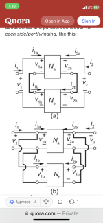
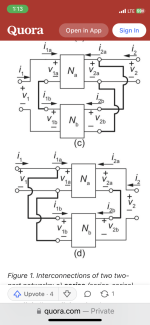
I found a few options of connection (see pictures). Please could some experts advise on the advantages/disadvantages of these connections?
Thank you!
I found 2 unit of 1000VA transformers with secondary output of 50V(10A) X 2.
Please correct me if I am wrong, there are some online information that suggested 2 identical transformers can be connected together to obtain double the current output.
Would the output be better connected before or after full bridge rectifier?
I found a few options of connection (see pictures). Please could some experts advise on the advantages/disadvantages of these connections?
Thank you!
Attachments

You won't be able to get 35VDC from a transformer secondary that is 50 VAC unless you use a DC voltage regulator.
A secondary voltage of 25 VAC is needed to get 35VDC from a simple full wave rectifier - capacitor supply.
As for the transformer wiring, yes you can wire two identical secondaries together for 2X current output as long as the phase is matched.
Wiring the secondaries from two "identical" transformers together is also possible as long as they are actually the same voltage.
I believed I can get +-35Vdc by employing a “floating ground”, that is connecting the 2 secondary output in parallel to a bridge rectifier, the output of bridge rectifier to 2 capacitors in series, and centre tap in between the 2 capacitors to be the floating ground. I haven’t done it before and I welcome advice whether a balanced +-35Vdc can be obtained with this method and what are the consequences, if any.
I believe another method is using method (a) in the picture. Where the output is halved, as there is only 1/2 the ac primary voltage.
Please feel free to correct me if I am wrong.
I believe another method is using method (a) in the picture. Where the output is halved, as there is only 1/2 the ac primary voltage.
Please feel free to correct me if I am wrong.
That works if and only if currents to ground are AC. Any DC component upsets the balance and ground moves off center. QSC used to do it with a lot of their older amps. They can get away with it because of the independent power supplies for each channel (required because of their topology). If the ground moves a little off center in one channel it doesn’t affect the other.
Can't comment on the floating ground idea.
Halving the primary voltage does give half the secondary voltage but now the max power (VA) from the transformer is also half.
I think it's always best to get the right transformer(s) for the job, from a reputable manufacturer, since we're dealing with the hazardous mains power and its safety issues.
That word 'ground' confuses me. Is it:
a] AC power Safety Ground/Protective Earth
b] Transformer primary ~ center tap
c] Transformer secondary ~ center tap
d] Secondary low voltage supply common
a] AC power Safety Ground/Protective Earth
b] Transformer primary ~ center tap
c] Transformer secondary ~ center tap
d] Secondary low voltage supply common
Good point, that was what Ibwas wondering too, but why would the VA be half? due to the primary winding wire thickness?Can't comment on the floating ground idea.
Halving the primary voltage does give half the secondary voltage but now the max power (VA) from the transformer is also half.
I think it's always best to get the right transformer(s) for the job, from a reputable manufacturer, since we're dealing with the hazardous mains power and its safety issues.
Yes, primary winding thickness becomes the limiting factor. But in practice you can get somewhat more than 50% of its rating with the same temperature rise. Copper losses go up, but core losses come down when operating at low flux density. A 1kVA dual primary strapped for 240 and then run at 120 will give half the secondary voltages at around 600 to 700 VA. You will also have a longer thermal time constant due to the increase in mass (compared to a 500 or 700 VA unit) so it can be run well over for longer periods before it reaches design temperature rise. It’s that temperature rise that ultimately limits it. At the typical 3.2A per sq mm design for transformers, the wire is being run at 50% of what it would be if it were in a conduit feeding a branch circuit. Even then it has some derating and can take a 5-10X overload for say, starting a motor, and still not be anywhere close to fusing.
It's simple math : V/2 x A = VA/2but why would the VA be half?
The secondary voltage is half but the available secondary current will remain the same due to wire size.
This is the theory, in practice it's a little more, as @wg_ski explained above.
The down side of running a transformer at half primary voltage is you have a physically larger and heavier transformer than you actually need for the job.
Maybe not a problem for your project since you mentioned switching between two different Vout.
You have to use two rectifiers of coarse. Even then there might be variation in turns' ratio so one x-frmr will be loaded more. It's called droop sharing.after full bridge rectifier
Anyhow it's generally not recommended. Either secondary in series, primary in parallel or vice versa. If the transformers of yours have split primary you may use 120 and connect pri in series and secondaries in parallel safe way . Beware of proper phasing.
Thank you all for your kind replies and advice.
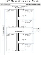
I got a reply from Talema as well and I thought I share the pictures that they sent me, not that you need those but more of a confirmation that they can be connected in such manner, I presumed without voiding the warranty ☺️
I got a reply from Talema as well and I thought I share the pictures that they sent me, not that you need those but more of a confirmation that they can be connected in such manner, I presumed without voiding the warranty ☺️
Attachments

- Home
- Amplifiers
- Power Supplies
- Multiple identical transformers parallel connections