Here's a bunch of tweaked BJT (both "vintage" and current) LTSpice models for your perusal, see attached and see this thread for details on the method I used. After posting it, I continued measuring and tweaking models for pretty much all the small signal and VAS/driver transistors I have in stock. At one point or another I've used all the models at least once and they seem to work fine, but the usual disclaimers apply: provided as-is, no express or implied warranty, no liability, etc.
These are the models included:
Small signal:
2N5088
2SC1775 / 2SA872
2SC1815
2SA1016
2SC2240 / 2SA970
2SC2291
BC183C
BC183L
BC547 / BC557
KSC945C / KSA733
KSC1845 / KSA992
LM394
MPS8099 / MPS8599
MPSA06 / MPSA56
MPSA18
MPSA42 / MPSA92
ZTX384 / ZTX214
ZTX653 / ZTX753
VAS/driver:
2SC1941
2SC2910
2SC3116 / 2SA1248
2SC3788
2SD600 / 2SB631
BD139 / BD140 (both Fairchild and STM)
/ KSA1142
KSC2690 / KSA1220
KSC3503 / KSA1381
MJE243 / MJE253
MJE340 / MJE350
TTC004B / TTA004B
Some random notes:
- The Peak Atlas DCA Pro provides a maximum Ic of about 10 mA and I don't really know how much you can extrapolate the accuracy of the model to higher currents. Bear this in mind especially for the VAS/driver models.
- Where I had a bunch of them, I measured beta and Vbe for the lot and based the model on the one closest to the median, but for some I only had one or two, so the model may not be as representative. Also, even where I had a bunch, the model will be representative of that particular bunch, the ones you have / buy may well be different, so ymmv. They were all pulled out of vintage equipment or bought from reliable suppliers (Mouser, Farnell, etc.). I'm not going to list all my stock, so if you have questions about a specific model, please ask.
- I have measured vs. simulated curves (Ic-Vce, hFE-Ic, Ic-Vbe and reverse) for all of them. Those are the direct measurements I've based the models on. I've also tweaked to match other things like beta droop, ft, Rb, temperature effects, etc. where those were available from the datasheet or elsewhere, which isn't always the case. If they weren't, I've left those parameters as they were in the model I tweaked or at their default value. If you're interested in the curves and/or details of a particular model, again please ask.
- This has been discussed before but it bears repeating: it's amazing how outrageously bad some of the models provided by the manufacturers are. Take for example the Toshiba TTC004B / TTA004B: it looks like they've tried to model the quasi-saturation apparent from the Ic-Vce curves in the datasheet by giving them a ridiculously bad VAF, when in fact they are excellent in that respect.
- On that note, given the difficulties with simulating quasi-saturation (see the thread above), I've only bothered with it where it was apparent in my measurements, but not where it appears only in the datasheet at voltages / currents where I don't envisage using that particular transistor, as in those Toshibas.
Can't think of anything else to say right now, comments and questions always welcome!
Cheers,
Cabirio
Update 14-Mar-25: Revision B attached, see post #8.
Attachments
Last edited:

Another note: as you can see, for a few of the models, there's also one by Bob Cordell and I've actually based mine on his. Needless to say his models are excellent, but I tweaked them anyway to match better my transistors and to include quasi-saturation where it's significant (e.g. the MJE340/MJE350). Also for practice, since the process can be quite tedious and the more you do, the more you get a feel for the effect of adjusting each parameter and the faster you arrive at a good match.
Hi cabirio,
Just wanted to say thanks for sharing your work. I've been using these in my sims for away now.
One question: What is the difference in BD139/BD140 and BD139S/BD140S. Is the "S" for modeling near saturation?
Just wanted to say thanks for sharing your work. I've been using these in my sims for away now.
One question: What is the difference in BD139/BD140 and BD139S/BD140S. Is the "S" for modeling near saturation?
Thanks for sharing your work.
As you may know, the TTC004B / TTA004B are used in the output stage of Nelson's Pearl 3 Phono Pre-Pre.
Many DIYAUDIO'rs have Tektronix 576 curve tracers, perhaps they can assist in providing some data.
Jack
As you may know, the TTC004B / TTA004B are used in the output stage of Nelson's Pearl 3 Phono Pre-Pre.
Many DIYAUDIO'rs have Tektronix 576 curve tracers, perhaps they can assist in providing some data.
Jack
The ones without S are from Fairchild (I bought them a while back, before the takeover by OnSemi) and they have isolated TO-126 packages; the ones with S are STM, I bought them more recently and they are non-isolated. I thought why not make a model for each, but the differences are rather subtle, really. I'm pretty sure it won't make much of a difference to your simulations whether you use one or the other.Hi cabirio,
Just wanted to say thanks for sharing your work. I've been using these in my sims for away now.
One question: What is the difference in BD139/BD140 and BD139S/BD140S. Is the "S" for modeling near saturation?
TTC004B / TTA004B: it looks like they've tried to model the quasi-saturation apparent from the Ic-Vce curves in the datasheet by giving them a ridiculously bad VAF, when in fact they are excellent in that respect.
Actually I think this is a case of the good old extraction process error. It looks like Vaf and Var have been swapped. Var is the Early voltage with collector and emitter swapped. This brings into question whether other parameters have been swapped like Re/Rc. Also, Vbe is too high at high currents for the P device because no value of Irb has been specified.
Attachments
Great Cabirio!Here's a bunch of tweaked BJT (both "vintage" and current) LTSpice models for your perusal, see attached and see this thread for details on the method I used. After posting it, I continued measuring and tweaking models for pretty much all the small signal and VAS/driver transistors I have in stock. At one point or another I've used all the models at least once and they seem to work fine, but the usual disclaimers apply: provided as-is, no express or implied warranty, no liability, etc.
These are the models included:
Small signal:
2N5088
2SC1775 / 2SA872
2SC1815
2SA1016
2SC2240 / 2SA970
2SC2291
BC183C
BC183L
BC547 / BC557
KSC945C / KSA733
KSC1845 / KSA992
LM394
MPS8099 / MPS8599
MPSA06 / MPSA56
MPSA18
MPSA42 / MPSA92
ZTX384 / ZTX214
ZTX653 / ZTX753
VAS/driver:
2SC1941
2SC2910
2SC3116 / 2SA1248
2SC3788
2SD600 / 2SB631
BD139 / BD140 (both Fairchild and STM)
/ KSA1142
KSC2690 / KSA1220
KSC3503 / KSA1381
MJE243 / MJE253
MJE340 / MJE350
TTC004B / TTA004B
Some random notes:
- The Peak Atlas DCA Pro provides a maximum Ic of about 10 mA and I don't really know how much you can extrapolate the accuracy of the model to higher currents. Bear this in mind especially for the VAS/driver models.
- Where I had a bunch of them, I measured beta and Vbe for the lot and based the model on the one closest to the median, but for some I only had one or two, so the model may not be as representative. Also, even where I had a bunch, the model will be representative of that particular bunch, the ones you have / buy may well be different, so ymmv. They were all pulled out of vintage equipment or bought from reliable suppliers (Mouser, Farnell, etc.). I'm not going to list all my stock, so if you have questions about a specific model, please ask.
- I have measured vs. simulated curves (Ic-Vce, hFE-Ic, Ic-Vbe and reverse) for all of them. Those are the direct measurements I've based the models on. I've also tweaked to match other things like beta droop, ft, Rb, temperature effects, etc. where those were available from the datasheet or elsewhere, which isn't always the case. If they weren't, I've left those parameters as they were in the model I tweaked or at their default value. If you're interested in the curves and/or details of a particular model, again please ask.
- This has been discussed before but it bears repeating: it's amazing how outrageously bad some of the models provided by the manufacturers are. Take for example the Toshiba TTC004B / TTA004B: it looks like they've tried to model the quasi-saturation apparent from the Ic-Vce curves in the datasheet by giving them a ridiculously bad VAF, when in fact they are excellent in that respect.
- On that note, given the dificulties with simulating quasi-saturation (see the thread above), I've only bothered with it where it was apparent in my measurements, but not where it appears only in the datasheet at voltages / currents where I don't envisage using that particular transistor, as in those Toshibas.
Can't think of anything else to say right now, comments and questions always welcome!
Cheers,
Cabirio
🙂
Revision B posted above. @CG spotted anomalies in the temperature dependence of Vbe for the KSC3503 and KSA1381 models (see here), so I've corrected parameter EG for those. I also went through all the models to double-check and made corrections to these:
- 2SC3788: the datasheet does provide Ic-Vbe plots at different temperatures but I must have overlooked it when I made the model.
- KSA1142, MJE340/MJE350: no plots available but with the previous EG value the Vbe temperature dependence looked suspect, so I've set EG to the default value of 1.11.
Thank you so much for generously sharing your work, @cabirio!
I would like to accept your invitation
I would like to accept your invitation
to make this request: If you have any fT-vs-Icollector data for the KSC2690/KSA1220 pair, would you post it please?I've also tweaked to match other things like beta droop, ft, Rb, temperature effects, etc. where those were available from the datasheet or elsewhere, which isn't always the case. If they weren't, I've left those parameters as they were in the model I tweaked or at their default value. If you're interested in the curves and/or details of a particular model, again please ask.
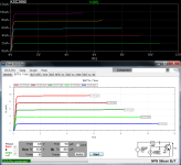
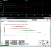
Sure, here they are, Fairchild datasheet vs. simulated:
KSC2690

KSA1220

Note that, generally, the sharper drop at high currents seen in the datasheet plots is due to quasi-saturation. In this particular case, my measurements at the currents available from the DCA75 analyzer didn't show any (see attached), and it would have been difficult to extrapolate to higher currents from the datasheet Ic-Vce plots, so no QS was included in the models.
It is possible to get a sharper high current drop in a model without QS, but then the shape of the whole curve changes and you get a poorer fit at lower currents. I guess it's a judgement call, but I don't think many people will be using these transistors at Ic's of more than half an amp, so I went for a pretty good fit all the way up to that sharp drop even if after it there's more deviation, rather than try to match the entire curve and get a poorer fit at the Ic values where you're much more likely to use these transistors.
KSC2690
KSA1220
Note that, generally, the sharper drop at high currents seen in the datasheet plots is due to quasi-saturation. In this particular case, my measurements at the currents available from the DCA75 analyzer didn't show any (see attached), and it would have been difficult to extrapolate to higher currents from the datasheet Ic-Vce plots, so no QS was included in the models.
It is possible to get a sharper high current drop in a model without QS, but then the shape of the whole curve changes and you get a poorer fit at lower currents. I guess it's a judgement call, but I don't think many people will be using these transistors at Ic's of more than half an amp, so I went for a pretty good fit all the way up to that sharp drop even if after it there's more deviation, rather than try to match the entire curve and get a poorer fit at the Ic values where you're much more likely to use these transistors.
Attachments
Last edited:
Thank you very much!
I don't know about others but I generally run these TO-126 devices at less than 20mA, so I'm interested in the left side of the plot and not the right side.
I don't know about others but I generally run these TO-126 devices at less than 20mA, so I'm interested in the left side of the plot and not the right side.
- Home
- Design & Build
- Software Tools
- Tweaked BJT LTSpice models