
I may have misunderstood the principle, but from what I gather the switching of diodes will not induce ringing if the secondary winding is properly damped upstream by the Cx//Cs+Rs snubber?
Ringing will be solved with an appropriate snubber, but the PIN diode effect described by Marcel will just be reduced, especially if the snubber is placed across the transformer winding.
Impedances in antenna like-structures tend to be pretty low, in the tens to hundreds of ohms, and the impedance of the wiring + the resistance part of the snubber will not shunt the diode perfectly.
The only way to achieve that up to VHF frequencies is to connect a ceramic cap directly across the diode.
Ordinary, slow diodes make excellent PIN diodes, they are even used in cheapo satellite signal switchers.
It is possible to use a direct capacitor to eliminate PIN effect modulation + a snubber taking into account the additional capacitor
Very entertaining pic. I rate mercury first, followed by conventional vacuum rectifiers, followed by GE, followed by synch, with damper diodes towards the bottom. Preferably half wave whenever possible.
Can we have the source of the image and a reference to the original thread please.here's something I posted
Tell me if I understand the picture correctly, in the case of a full-wave bridge, each of the four diodes would have an inductor/resistor fitted on it?
I've looked at this possible problem in my home brewed vacuum tube amplifiers and basically, it's a nothingburger.In my book , yes, windings become disconnected below 0.7V ... but at the same time it means such disconnection happens at very low voltage, current and energy level, making such disconnection quite irrelevant.
It is not as if, say, disconnection happened at 20 - 30 - 40V
Personally do not lose sleep about it.
The day somebody shows me "horrible 50-60Hz artifacts" in signal output I might begin to worry ..... until then ....
Would also love to see side by side waveforms showing "with-without" capacitor situations.
Until then .....
It was shoe-box compact cassette recorders that used to pick the noise up in the head pre-amps back in the 1970s.
Fast diodes are so cheap and mass produced that there is little point in using slow ones these days.
I have never seen a ceramic cap fail when it is being used to bypass an old diode.
Just fit them and forget resistors and chokes.
Fast diodes are so cheap and mass produced that there is little point in using slow ones these days.
I have never seen a ceramic cap fail when it is being used to bypass an old diode.
Just fit them and forget resistors and chokes.
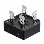
Solid state power amplifier equipment very often uses one or more bridge rectifier assemblies, usually rated 35 amperes continuous or sometimes 50 amperes(!), packaged in a "GBPC" package as shown below. The diodes inside these bridge assemblies are just as "slow" as their 1N4007 little brothers: reverse recovery time of 2000 to 3000 nanoseconds. For those applications, "just use a fast diode" is not useful advice, since that increases both cost and heatsink area.
Luckily, the Quasimodo approach tolerates "slow" diodes quite well, and a lot of DIY power amps here on diyAudio use GBPC bridges + QM derived smootheners.
_
Luckily, the Quasimodo approach tolerates "slow" diodes quite well, and a lot of DIY power amps here on diyAudio use GBPC bridges + QM derived smootheners.
_
Attachments
- Home
- Design & Build
- Electronic Design
- Ceramic capacitors as diode bypasses for power supply rectifier