Hi, I'm working on a 2 in 6 out crossover for my audio system. I have a wondom apm2 with 4 dacs + 4 i2s out, so I had to add an external dac as well (https://www.audiophonics.fr/en/dac-and-interface-modules/dac-pcm5102mk-i2s-p-10551.html).
Tried setting up a 500hz test signal on all outputs in Sigma Studio and got this. dac{0,1,2,3} look like the purple while dig{0,1} look like the green.
Any clues why this is?
Tried setting up a 500hz test signal on all outputs in Sigma Studio and got this. dac{0,1,2,3} look like the purple while dig{0,1} look like the green.
Any clues why this is?
Attachments
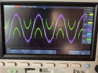

Not sure, but it may also be due to a format problem (I2S vs Sony) or MSB first vs LSB first.
DACs usually include some kind of anti-windup algorithm to give regular clipping like the analogue circuits do.
DACs usually include some kind of anti-windup algorithm to give regular clipping like the analogue circuits do.
My vote is confusing I2S with LJ. Sending LJ to a chip in standard I2S mode will multiply by 2 and wrap-around the values just like the green trace.
Not sure, but it may also be due to a format problem (I2S vs Sony) or MSB first vs LSB first.
Could be - if the LRCK/WS moves one bit-time in the wrong direction relative to the data, the result is digital gain or attenuation by 6dB.
I have encountered this situation. As you said, it is caused by displacement (I2S and left-aligned MSB are inconsistent)My vote is confusing I2S with LJ. Sending LJ to a chip in standard I2S mode will multiply by 2 and wrap-around the values just like the green trace.
When using the Tone unit, you need to pay attention. It outputs directly at 0dBFs, which means that your output unit has reached full amplitude.Hi, I'm working on a 2 in 6 out crossover for my audio system. I have a wondom apm2 with 4 dacs + 4 i2s out, so I had to add an external dac as well (https://www.audiophonics.fr/en/dac-and-interface-modules/dac-pcm5102mk-i2s-p-10551.html).
Tried setting up a 500hz test signal on all outputs in Sigma Studio and got this. dac{0,1,2,3} look like the purple while dig{0,1} look like the green.
Any clues why this is?
But your problem is probably caused by the inconsistent alignment of the audio format.
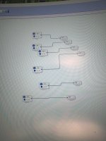
I'd start by checking the I2S settings first. The DAC has a jumper that selects either I2S or Left Justified (LJ) mode. I attached a screenshot of the 1701's I2S settings. IIRC these are the defaults. The 1701's crystal on that board is 12.288 MHz. The 1701's internal clock is 4 times that or 49.152 MHz. So:
Frame Sync Type = LRCLK
Frame Sync Freq = internal clock / 1024 = 48 KHz
MSB Position = delay by 1 if DAC jumper is in I2S position, delay by 0 if DAC jumper is in LJ position
Word length = whatever you want
BCLK Frequency = internal clock / 16 = 3.072 MHz
Also remember the max 1701 DAC voltage is 0.5 V while the max PCM5102 DAC voltage is 2.0 V.
Hope this helps...
Thanks, this was it. Tried to play around with I2S settings but got an even more messed up waveform. Putting a -20dB volume control in Sigma Studio solved it.Looks like 'digital wrap-around' i.e. too much gain somewhere.
A bit worried still that it's caused by improper settings like @abraxalito said and I now just put a band aid on top 🙂. Works though.
- Home
- Source & Line
- Digital Line Level
- Help explain weird waveform by i2s DAC