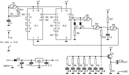
The attached schematic for a pink noise generator of which various versions can be found on the net, seemed easy to build. I have build a kit version with pcb. However, it appears to have an issue. Upon start all works fine, but within no time something makes it oscillate far more than intended. What a pun. The issue takes the regulator (78L08) and IC1 resp. IC2 (CD4066BE) down. The N1-4 IC (CD4093BE) has survived several times. A lab supply of 12Vdc was used to power the unit.
Before re-placing the regulator and IC1, IC2 for a second try, a decoupling cap of 100nF was added at the supply pin of each IC. Alas, the second time went the same dead end. A search revealed this is not the first time with this schematic, but no remedy could be found, apart from the decoupling.
Any suggestion on what is going on and how to cope with it?
Edit: the IC1, IC2 are CD4006BE (not 4066), but as per post 4 this should not matter.
Attachments
Last edited:
What a complicated circuit.
I use a BC107 upside down, base connected to the collector and feed it with 10mA and amplify the white noise. A simple tone shaper gives the desired values for pink noise.
Very simple and always works.
BC107 transistors are very noisy when fed upside down.
I use a BC107 upside down, base connected to the collector and feed it with 10mA and amplify the white noise. A simple tone shaper gives the desired values for pink noise.
Very simple and always works.
BC107 transistors are very noisy when fed upside down.


IC1 and IC2 should be CD4006, an 18-stage shift register. The circuit implements a 33-bit maximal-length LFSR with a tap at bit 20.The issue takes the regulator (78L08) and IC1 resp. IC2 (CD4066BE) down.
Ed
In other words : this is a very basic white noise generator with pink noise filter.
R10 and "the rest" form the filter. You can use FM inter station noise as white
noise to a good approximation.
R10 and "the rest" form the filter. You can use FM inter station noise as white
noise to a good approximation.
The circuit might not be the best or the smartest, but it should work alright. CMOS circuits can take a lot of abuse and survive, and the 78L08 can only die if its input polarity is inverted, or if the input voltage exceeds ~40V.
Strange.
Probably supply-related
Strange.
Probably supply-related
Yes, of course.
However, it doesn't explain why the ICs and regulator are popping.
At worst, they should moderately overheat.
There has to be something else
However, it doesn't explain why the ICs and regulator are popping.
At worst, they should moderately overheat.
There has to be something else
Semiconductor avalanche noise is a simple source of white noise. Pink noise maybe obtained by filtering it appropriately.
With a 8V supply, just a few mA/input and anyway the total current will not exceed ~100mA. That would be 0.8W for the whole circuit and 0.4W for the regulator with a 12V supply, but that's the upper theoretical limit, the actual current will be lowerFloating inputs to a 4066 will cause a lot of current drain.
Yes, everyone here already owns a high-quality noise generator (when playing an appropriate file).
Ed
Ed
Floating inputs are likely oscillating and exceeding the supply rails leading to latch-up. But it doesn't matter. The problem was the wrong chip. Yes, the odds of another mistake are high, but we cannot help with that.With a 8V supply, just a few mA/input and anyway the total current will not exceed ~100mA. That would be 0.8W for the whole circuit and 0.4W for the regulator with a 12V supply, but that's the upper theoretical limit, the actual current will be lower
Sure, but you probably have other things you need your computer doing. And a computer with DAC/soundcard is a lot of baggage for just this job. If the computer is also running an FFT then the cost/benefit picture looks a bit better. Someone should post a RPi/Arduino AWG in DIYA. Problem is that those who can, probably can't be bothered. Running Audacity is probably close enough.In 2024 isn't easier to just download (or generate) a digital file?
Small microcontroller is all thats needed for an LFSR generator, ATtiny or something like that. If you want a bit more sophistication use one with a DAC and Stenzel's algorithm https://github.com/Stenzel/newshadeofpink/blob/master/newshadeofpink.pdf
- Home
- Design & Build
- Equipment & Tools
- Pink noise generator