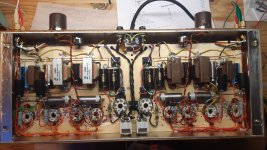
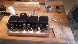
A nice and simple amp, but efficiency is terrible..
Used with full range speakers (Fane 12-250TC), 2-3W seems to be enough most of the time so I tried first everything triode connected.
I may try the 6AC7 in pentode mode, because gain is a little bit low.
Why not 6V6's in pentode mode too, and plate to cathode feedback.
To me, it sounds quite good, but no "magic". Not soft, not harsh, without NFB.
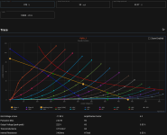
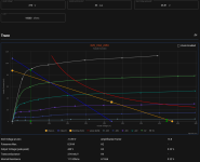
6V6 may not look very sexy triode connected when looking at the curves, but they seem to perform well.
Have to try the zener trick between grid/cathode of the 6V6, to minimize blocking distorsion, may be interesting for low power amps..
Used with full range speakers (Fane 12-250TC), 2-3W seems to be enough most of the time so I tried first everything triode connected.
I may try the 6AC7 in pentode mode, because gain is a little bit low.
Why not 6V6's in pentode mode too, and plate to cathode feedback.
To me, it sounds quite good, but no "magic". Not soft, not harsh, without NFB.
6V6 may not look very sexy triode connected when looking at the curves, but they seem to perform well.
Have to try the zener trick between grid/cathode of the 6V6, to minimize blocking distorsion, may be interesting for low power amps..
Attachments
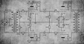


Looks like a fundamentally good circuit.
However, for RC coupling from stage to stage, I am not convinced that either a diode, or a zener diode will reduce blocking distortion.
Any diode current, any zener diode current, or any grid current will all do the same thing . . .
They will draw current through the coupling capacitor, and as a result, will change the voltage across the cap (which causes a different bias voltage versus the quiescent state bias voltage).
Perhaps I am missing something . . . about a diode or a zener diode that is connected from the control grid to the cathode. Am I wrong?
If I was worried about efficiency, I would own a Class D switching amplifier, or at least own a solid state amplifier.
For me, only vacuum tube amplifiers.
Oh, and I am making it easy for the mains power company: I use choke input B+ filters, and the amplifiers total power factor is about 0.9.
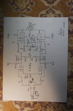
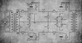
I am attaching the schematic of my 5881 balanced amplifier.
Sorry, I can not even find my own Post about that amplifier in Tubes/Valves; I am an idiot about using software, and searches.
Help Please, can anybody find my Original Post of my balanced amplifier.
Thanks!
However, for RC coupling from stage to stage, I am not convinced that either a diode, or a zener diode will reduce blocking distortion.
Any diode current, any zener diode current, or any grid current will all do the same thing . . .
They will draw current through the coupling capacitor, and as a result, will change the voltage across the cap (which causes a different bias voltage versus the quiescent state bias voltage).
Perhaps I am missing something . . . about a diode or a zener diode that is connected from the control grid to the cathode. Am I wrong?
If I was worried about efficiency, I would own a Class D switching amplifier, or at least own a solid state amplifier.
For me, only vacuum tube amplifiers.
Oh, and I am making it easy for the mains power company: I use choke input B+ filters, and the amplifiers total power factor is about 0.9.
I am attaching the schematic of my 5881 balanced amplifier.
Sorry, I can not even find my own Post about that amplifier in Tubes/Valves; I am an idiot about using software, and searches.
Help Please, can anybody find my Original Post of my balanced amplifier.
Thanks!
Attachments
Last edited:
I found my original posting:
https://www.diyaudio.com/community/threads/low-power-balanced-mono-block-tube-amplifier.404771/
I hope you like it.
https://www.diyaudio.com/community/threads/low-power-balanced-mono-block-tube-amplifier.404771/
I hope you like it.
You are basically getting a step-down with the IT connected for balanced operation.A nice and simple amp, but efficiency is terrible..
Used with full range speakers (Fane 12-250TC), 2-3W seems to be enough most of the time so I tried first everything triode connected.
I may try the 6AC7 in pentode mode, because gain is a little bit low.
Why not 6V6's in pentode mode too, and plate to cathode feedback.
To me, it sounds quite good, but no "magic". Not soft, not harsh, without NFB.
6V6 may not look very sexy triode connected when looking at the curves, but they seem to perform well.
Have to try the zener trick between grid/cathode of the 6V6, to minimize blocking distorsion, may be interesting for low power amps..
To get more efficiency you definitely need to make the most of the 6P6s and use it at its max anode voltage of 350V, especially because you are using 10K load. Just keep dissipation within 10W and it will be just fine. You should get 5W at least. Even more gain will be needed for this.....
The cathode bias resistor with 350 anode voltage should be about 1K (i.e. 378V supply voltage distributed as 350V anode voltage + 28V bias). Still class A operation.
When using cathode bias + large grid resistor + grid stopper, in my opinion you don't need a "nasty" zener. You might just need to optimize the stopper value to get the most favourable time constant (formed with the input capacitance).
Last edited:
Thank you 6A3sUMMER and 45.
I did not try it yet, and as I don't push the volume on this amp..
The 50K pot at input is fine tune the symetry?
I like too having meter(s) to monitor cathode current, unfortunately no space left on this chassis.
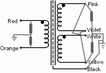
Isn't it a 1:1 ratio the way it is wired? I didn't measure this..
As I understand, if the two primaries were not "center tapped" , it would be a 2:1 ratio.
I may be wrong.
B+ is only 280V, if more power will be needed, it will be pentode connected for this amp.
I'll do it one day, out of curiosity.
Yes, that's right. I have read this in MerlinB book, it seems to work well from his experimentation.Perhaps I am missing something . . . about a diode or a zener diode that is connected from the control grid to the cathode. Am I wrong?
I did not try it yet, and as I don't push the volume on this amp..
Yes!I hope you like it.
The 50K pot at input is fine tune the symetry?
I like too having meter(s) to monitor cathode current, unfortunately no space left on this chassis.
You are basically getting a step-down with the IT connected for balanced operation.
Isn't it a 1:1 ratio the way it is wired? I didn't measure this..
As I understand, if the two primaries were not "center tapped" , it would be a 2:1 ratio.
I may be wrong.
B+ is only 280V, if more power will be needed, it will be pentode connected for this amp.
I'll do it one day, out of curiosity.
Attachments
As I see it, you are using it in reverse mode, balanced to balanced, so it's the full secondary to full primary. The primary (i.e. the secondary in your schematics) has a virtual center tap created with the resistors. So I think it's 2:1.
emk2,
I should explain about the 50k potentiometer of my balanced amplifier:
( https://www.diyaudio.com/community/threads/low-power-balanced-mono-block-tube-amplifier.404771/ )
The 50k Potentiometer (connected as a rheostat) is the Volume Control.
The 7 resistors from the XLR connector to the 2 input triode's grids is a Shunt Volume Control.
With perfectly matched fixed resistors, the volume control tracking is always perfectly balanced.
The 50k potentiometer, who cares?, it has nothing to do with balance (the balance from XLR to the 2 grids is Intrinsic).
From the XLR connector, we have:
2 Rg resistors to return the grids to ground if the signal source does not do that; 2 Series resistors as part of the shunt attenuator volume control; 50k shunt volume control rheostat; and 2 grid stopper resistors.
7 resistors, but only 3 resistors in the Shunt Attenuated Volume Control.
With the 50k turned to 50k, the shunt volume control looses about 3dB, versus the voltage at the XLR (perfectly acceptable, because XLR differential signal is 6 dB more than a single ended RCA connector signal).
Keep designing, building, and listening!
Last edited:
You were right, 2V RMS input to 0.83V out (6J4 grids).As I see it, you are using it in reverse mode, balanced to balanced, so it's the full secondary to full primary. The primary (i.e. the secondary in your schematics) has a virtual center tap created with the resistors. So I think it's 2:1.
2.4:1 instead of 2:1 (probably due to 5K virtual CT resistors)
I have to wire the Sowter 8920 like this for 1:1 I guess.
Should work with 10K resistors.. as the DAC ouput Z is about 50 ohms.
Thanks 6A3sUMMER, I didn't get it about the volume control.
I could discard the input transformers but it provides an isolation.
Attachments
- Home
- Amplifiers
- Tubes / Valves
- 6V6 balanced amp