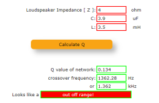
Wikipedia told me that "a second-order low-pass filter with a very low quality factor has a nearly first-order step response", so did the VituixCAD2 software. In the CAD, I tried by simulating a 4 Ohms woofer series connected to a 3.5mH inductor for the first-order configuration and then added a very small capacitor--here is 3.9uF--parallel to the woofer for creating the second-order configuration, with extremely low Q-factor. The frequency responses and the impedance curves of the two cases are nearly identical. Are there any other differences between them? What are pros and cons between these two cases?


Last edited by a moderator:

Could you please explain the "2 second order systems cascaded" in detail? And also, how did you find the pole frequencies?Your pole frequencies are widely separated (182Hz and 10kHz) that it behaves as 2 second order systems cascaded. Essentially the cap is doing nothing till about 10kHz.
Could you please explain the "2 second order systems cascaded" in detail?
The number of poles is nothing but the order of the system. When cascaded, two poles result in a second order system. However, for an LC filter, the poles are always complex conjugates (a+/-jb) and therefore at the same physical frequency. When the Q-factor is low, the second order behaviour manifests at a much higher frequency, as the transition region is widened.
Nevertheless, one could cook up a second order filter using two first order ones (with faraway cutoff freqs), and in that case, the slope will be first order (-6dB/oct) until the second pole occurs whereafter it would become second order (-40dB/dec or -12dB/oct).
Last edited:
Could you please explain the "2 second order systems cascaded" in detail? And also, how did you find the pole frequencies?
Pretty sure he meant 2 first-order systems cascaded.
However, for an LC filter, the poles are always complex conjugates (a+/-jb) and therefore at the same physical frequency.
Only when Q >= 1/2.
There’re many posts, no one answers my questions straightly though.
1. Has anybody ever found Q of lower than 0.3 in real use?
2. What are pros and cons of Q of lower than 0.5?
3. What are differences between using first-order and second-order with extremely low Q (Q < 0.5)?
1. Has anybody ever found Q of lower than 0.3 in real use?
2. What are pros and cons of Q of lower than 0.5?
3. What are differences between using first-order and second-order with extremely low Q (Q < 0.5)?
Since your first post, I have been playing around with simulation. I found that I can mimic a first order filter with a second order filter by adjusting the Q and the Fc. Both the magnitude and phase are mimicked so closely that the plots are within a pixel of each other. This holds true for high pass, low pass, and shelf filters. As far as I know, if the magnitude and phase response of two filters are the same, then the filters are the same.
i have found that a shelf filter with a Q of about 0.3 can introduce a uniform slope that extends from 100 Hz to 10 kHz.Has anybody ever found Q of lower than 0.3 in real use?
More information on the uniform slope using a low q shelf filter...
https://www.diyaudio.com/community/...e-wide-band-uniform-slope.391415/post-7152433
https://www.diyaudio.com/community/...e-wide-band-uniform-slope.391415/post-7152433
Yes, thank you Marcel.Only when Q >= 1/2.
The discriminant of the characteristic equation (i.e. b^2-4ac in ax^2+bx+c) is positive when Q<0.5 and the roots are real and unequal. It is fairly easy to guess what happens at Q=0.5.Could you please explain the "2 second order systems cascaded" in detail? And also, how did you find the pole frequencies?
The characteristic equation for all types (LP/HP/BP/AP) is the same:
Obtain discriminant (put x=s) and use the quadratic formula to solve.
What are differences between using first-order and second-order with extremely low Q (Q < 0.5)?
As the Q goes lower, we depend more and more on the 'R' or the speaker impedance (Q = Lw/R), which unfortunately is not a resistance, as expected by the transfer function. This deviation could possibly give more anomalies in the frequency response than otherwise expected.
Last edited:
This brings to my mind Cauer (or Duelund) elliptic cascaded filters. This happens actually quite easily acoustically as combination of electric 1st and a driver's natural roll-off. Quite easy with multiway dsp
The problem is how to protect tweeter and how to suppress woofer's cone resonance peak. Best application is with 3-way and a very smooth midrange. Obvious benefit of elliptic vs true 1st is reduced thd and imd.
https://www.diyaudio.com/community/threads/elliptical-crossovers.338533/
https://www.magicoaudio.com/crossovers
Troels Gravesen has severals speakers with these http://www.troelsgravesen.dk/CNO-GRANDE.htm
https://sound-au.com/articles/ntm-xover.htm
https://www.duelundaudio.com/en-us/steen-duelund/
John Kreskosky explains it by mathematics here https://musicanddesign.speakerdesign.net/Duelund_and_Beyond.html

p.s. I tried to get 1st order like step response dor my 4-way AINOgradient, but it turned out too difficult. Now I'm happy with 2nd order elliptic

The problem is how to protect tweeter and how to suppress woofer's cone resonance peak. Best application is with 3-way and a very smooth midrange. Obvious benefit of elliptic vs true 1st is reduced thd and imd.
https://www.diyaudio.com/community/threads/elliptical-crossovers.338533/
https://www.magicoaudio.com/crossovers
Troels Gravesen has severals speakers with these http://www.troelsgravesen.dk/CNO-GRANDE.htm
https://sound-au.com/articles/ntm-xover.htm
https://www.duelundaudio.com/en-us/steen-duelund/
John Kreskosky explains it by mathematics here https://musicanddesign.speakerdesign.net/Duelund_and_Beyond.html
p.s. I tried to get 1st order like step response dor my 4-way AINOgradient, but it turned out too difficult. Now I'm happy with 2nd order elliptic
Last edited:
I cannot see how you would achieve the typical elliptical characterstic from that combination. Where would the all important notch at the start of the stop-band come from?This brings to my mind Cauer (or Duelund) elliptic cascaded filters. This happens actually quite easily acoustically as combination of electric 1st and a driver's natural roll-off. Quite easy with multiway dsp
And the Duelund "filler driver" XO and its approximations also don't any show elliptic behavior.
KSTR, I don't understand mathematics... Just looking at pics of slopes and trying to understand what Kreskovsky wrote. And playing a lot with dsp and acoustic measurements - spl response, phase, step, distortion etc. Hypex and minidsp have preset high- and slowpass slopes which can be cascaded, but parametric eq options give even more possibilities to set slopes and correct irregularities.
https://musicanddesign.speakerdesign.net/Duelund_and_Beyond.html
On-axis raw response of Audax HM100Z0 in my Avalanche 3-way. In-room measurement.

Audax response with dsp eq and xo. Not a Duelund-filler but as wide range mid. In-room with lots of artefacts below 600Hz...

https://musicanddesign.speakerdesign.net/Duelund_and_Beyond.html
On-axis raw response of Audax HM100Z0 in my Avalanche 3-way. In-room measurement.
Audax response with dsp eq and xo. Not a Duelund-filler but as wide range mid. In-room with lots of artefacts below 600Hz...
- Home
- Loudspeakers
- Multi-Way
- First-order vs. Second-order with extremely low Q