H
HAYK
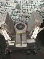
I have this amp for 15 years in classA 50w, see picture bellow.
At that time I could find from a nearby vendor 2sk2182 as best.
I simplified to minimum keeping decent damping of 40.
This amp is intended to those like me are convinced good sounds come from simple circuits.
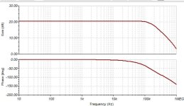
It has 0.1% @20khz by far inferior to any speaker. It can make very reliable instrument amp.

At that time I could find from a nearby vendor 2sk2182 as best.
I simplified to minimum keeping decent damping of 40.
This amp is intended to those like me are convinced good sounds come from simple circuits.
It has 0.1% @20khz by far inferior to any speaker. It can make very reliable instrument amp.
Attachments

I am far, very far from being an expert but with time I generally understand more or less a pattern.
Here I am unable to understand yours and I do not understand whether Class A or B, especially with the photo illustration and these big heatsinks.
Can you explain a little more because I am also a fan of the simplest possible amps.
Here I am unable to understand yours and I do not understand whether Class A or B, especially with the photo illustration and these big heatsinks.
Can you explain a little more because I am also a fan of the simplest possible amps.
H
HAYK
Sorry for ambiguity.
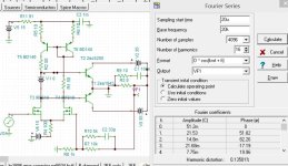
This is the classB version of the amp shown. As it is classA biased, both outputs amplify together, for that I didn't use current mirror just two resistors for common sources and other to balance drain voltages.
Bellow is better balanced circuit.
I'll explain the function later.

This is the classB version of the amp shown. As it is classA biased, both outputs amplify together, for that I didn't use current mirror just two resistors for common sources and other to balance drain voltages.
Bellow is better balanced circuit.
One pair output to limit 65W.How much max power do it put out?
I'll explain the function later.
Last edited by a moderator:
So, what class is it? A or B?
In the general sense, this is class B, because there is a bias necessary for the operation of transistors and for class B it is not zero. Not to be confused with class C. And of course this is not class A, because... the voltage offset is not fixed relative to the power buses of the power transistors. A high bias voltage is necessary to increase the linearity of transistors. Class AB is still class B with increased current)))
Therefore, it is a type of "class AB, with a floating bias source".
For class B with minimal bias, it was necessary to introduce a deep NBF and improve the transient characteristics, which is practically impossible to do in a circuit with a minimum set of parts, so the initial current rises as in class A.
An example is symmetrical push-pull amplifier circuitry, such as Krell, which can operate in class AB, but with a large initial current, until the current swing exceeds the set initial current, amplifier will operate in class A.
Last edited:
You can make a minimum bias for the initial section of power transistors, and this will be class B, due to the floating bias there will be no switching distortions as are used to class B with a fixed bias, but and they will work with great nonlinearity. The author-engineer decides how to make the circuit linear or nonlinear.This is the classB version of the amp shown.
H
HAYK
This amp is intended to those like me are convinced good sounds come from simple circuits.
If you do not know yet, have a look on Renardson amps : seven transistors, very low distorsion.
https://www.angelfire.com/ab3/mjramp/mjr7-mk5.html
I think of a mixing of a Renardson's input and a Transnova output.
H
HAYK
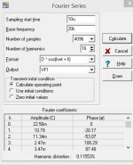
The distortion @20khz reaches 1% just 34.89Vp, pouring 76w.
Some more details "bichoné" for @huggygood.

Some more details "bichoné" for @huggygood.
Attachments

According to Renardson, you gave a link to the wrong diagram, probably this one was meant: https://www.angelfire.com/ab3/mjramp/newamp2.htmlIf you do not know yet, have a look on Renardson amps : seven transistors, very low distorsion.
https://www.angelfire.com/ab3/mjramp/mjr7-mk5.html
This circuit is interesting due to its distortion compensation circuit in the output stage. In this case, the implementation of class B is carried out due to the different operating modes of the upper and lower power transistor. The upper arm of the power transistor always operates in class A and the negative NFB circuit is never broken, while the lower arm operates with a current cutoff (class B), which reduces the likelihood of uncontrolled through currents.
There is only one voltage amplification cascade, due to which a large margin of stability and a high rate of rise in the NFB loop are obtained.
In general, this is a different principle for forming the operating mode of the output stage and it does not intersect with the principle of the author of this topic.
This is not the best solution, because the maximum input voltage for the base of the first transistor is not very high, so the NFB signal from the amplifier output goes there, but if you like, you can use it.I think of a mixing of a Renardson's input
and again, this "input" has nothing to do with the author’s circuit design of this topic..
- Home
- Amplifiers
- Solid State
- Pure classB transnova amplifier