Hah, MUFF & PUFF mystery. 😀
Is there a chance that puck gate remained charged at the moment of disassembly. With practically nonexistent gate leakage, charge would provide DS conduction for hours if not for days. I just checked with one MOSFET. After just touching gate with several V, it is happily measuring DS short circuit for hours after disconnection.
Is there a chance that puck gate remained charged at the moment of disassembly. With practically nonexistent gate leakage, charge would provide DS conduction for hours if not for days. I just checked with one MOSFET. After just touching gate with several V, it is happily measuring DS short circuit for hours after disconnection.
Yes this could be.
In the end I think I will need to try to sacrifice a pair to see if I get same behavior.
In the end I think I will need to try to sacrifice a pair to see if I get same behavior.
no need for sacrifice, just repeat simple DMM test tombo explained
I've seen your asc file....... and there is no bulb moment from my side
I think it's most elegant and clever to resort to regular optocoupler solution, as Pa did show in dozen of examples
you'll get nice and soft rise of Iq
I've seen your asc file....... and there is no bulb moment from my side
I think it's most elegant and clever to resort to regular optocoupler solution, as Pa did show in dozen of examples
you'll get nice and soft rise of Iq
When the current mirror gets the minimum required current to work the overshoot in the bias current is 10% and it rises slowly.
Pa solution is very nice but having the sense resistors a bit bigger in value has a bit worse performance when the amp drives loads <4ohm. I have 3.4r impedance speakers.
The sense resistor being smaller it cooks less at higher bias currents.
Even if a bit more complicated, for my speakers this fits a bit better.
I checked this and it’s not the case.Is there a chance that puck gate remained charged
I think I have something new to play with.
Recently a friend gifted me some nice and big heatsinks so now I can use these pucks safely at a bit higher power dissipation than before when I used them with the small heatsinks and they were going into thermal runaway, yes.. earlier when I said they were shorting DS and coming back to life after cooling was because I heated them too much and Rds dropped so low that it behaved like a short circuit.
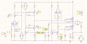
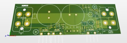
I combined the sePP ops with a front end and a dc servo(to keep ~1/2 rail voltage at the amp output). It uses a single rail power supply and from simulation it can give 50w/8r or 100w/4r at low thd
I will open a dedicated thread when the pcbs will get here and I will build the amp.
I have the same lousy symbols in my schematic...sorry about this one, not much that I can do about it.
😎
Recently a friend gifted me some nice and big heatsinks so now I can use these pucks safely at a bit higher power dissipation than before when I used them with the small heatsinks and they were going into thermal runaway, yes.. earlier when I said they were shorting DS and coming back to life after cooling was because I heated them too much and Rds dropped so low that it behaved like a short circuit.
I combined the sePP ops with a front end and a dc servo(to keep ~1/2 rail voltage at the amp output). It uses a single rail power supply and from simulation it can give 50w/8r or 100w/4r at low thd
I will open a dedicated thread when the pcbs will get here and I will build the amp.
I have the same lousy symbols in my schematic...sorry about this one, not much that I can do about it.
😎
Attachments


Hmm almost forgotten about this thread.
When I recently seen the news about the SIT5 first thing that came to my mind was the SePP OS because lately I was working to adapt all the cores of Gaincore to work with SePP).
Pa mentioned about 20% mos contribution to the overall current gain in the OS. With the SePP this adjustment is easily done thanks to ZM.
So these days I connected the SePP with a 2sk182es and a ixfn280n085. Maximum mosfet gain that can be had is a bit more than 50% with the installed components.
It measures good at 50% mos gain but the sound is not so engaging. Then I lowered the mosfet gain to 20%. Well even if the thd is a bit higher it sounds more present and with more authority.
As I setup the circuit it goes to a maximum of 2.2A bias because the heatsinks can`t take more without forced cooling. Probably the next days I will modify it to be able to get to a higher bias like 3-3.3A and for sure will add some fans.
Initially had the amp biased at 1.8A and took 2 measurements with this bias.


Only two measurements because the 3rd hd getting higher than 2nd hd means the amp wants more bias if you want to keep it 2nd hd dominant so I went with the bias at 2.2a, the maximum I could get for now. Took again the measurement at 10w/8r and a few more.


Then I changed the load to 4r.

With 4r already at 10w the amp starts to indicate it wants more bias to remain h2 dominant but as I said for now 2.2A is the maximum.


So because of the low bias and also the low contribution of the mosfet to the overall current gain at 27W the amp is close to clipping and the phase of h2 shifted. Don`t like this stuff in my amp because I can hear it.
To go further with the measurements I increased the gain of the mosfet to 50% to show what it can do into low impedances. If you need the higher power by all means and don`t have enough heatsinking you can trade some SIT sound signature and increase the gain on the mos.

When biased properly the amp is positive h2 dominant on the entire power bandwidth. To make it negative you can easily switch the polarity of the speakers as Pa thought us.
As power supplies I use MW SP-320-48, one for each channel. I use them without hf filtering and without the fans.
When I recently seen the news about the SIT5 first thing that came to my mind was the SePP OS because lately I was working to adapt all the cores of Gaincore to work with SePP).
Pa mentioned about 20% mos contribution to the overall current gain in the OS. With the SePP this adjustment is easily done thanks to ZM.
So these days I connected the SePP with a 2sk182es and a ixfn280n085. Maximum mosfet gain that can be had is a bit more than 50% with the installed components.
It measures good at 50% mos gain but the sound is not so engaging. Then I lowered the mosfet gain to 20%. Well even if the thd is a bit higher it sounds more present and with more authority.
As I setup the circuit it goes to a maximum of 2.2A bias because the heatsinks can`t take more without forced cooling. Probably the next days I will modify it to be able to get to a higher bias like 3-3.3A and for sure will add some fans.
Initially had the amp biased at 1.8A and took 2 measurements with this bias.
Only two measurements because the 3rd hd getting higher than 2nd hd means the amp wants more bias if you want to keep it 2nd hd dominant so I went with the bias at 2.2a, the maximum I could get for now. Took again the measurement at 10w/8r and a few more.
Then I changed the load to 4r.
With 4r already at 10w the amp starts to indicate it wants more bias to remain h2 dominant but as I said for now 2.2A is the maximum.
So because of the low bias and also the low contribution of the mosfet to the overall current gain at 27W the amp is close to clipping and the phase of h2 shifted. Don`t like this stuff in my amp because I can hear it.
To go further with the measurements I increased the gain of the mosfet to 50% to show what it can do into low impedances. If you need the higher power by all means and don`t have enough heatsinking you can trade some SIT sound signature and increase the gain on the mos.
When biased properly the amp is positive h2 dominant on the entire power bandwidth. To make it negative you can easily switch the polarity of the speakers as Pa thought us.
As power supplies I use MW SP-320-48, one for each channel. I use them without hf filtering and without the fans.
With the SePP this adjustment is easily done thanks to ZM.
Oh yeah
ZM likes Zen Amount Pots; wherever I see some free spot, I place one
usually set to MAX

You said "When biased properly the amp is positive h2 dominant on the entire power bandwidth"
Doesn't a positive phase H2 in REW mean a negative phase H2, as Nelson taught us?😎
Doesn't a positive phase H2 in REW mean a negative phase H2, as Nelson taught us?😎
could you share the values of resistors and the transistors used in your schematics?
front end without NFB seems interesting
or is there an NFB via IC1?
front end without NFB seems interesting
or is there an NFB via IC1?
Brave as alwaysusually set to MAX

You are right with this one, in this case the results are even better if one is chasing -h2 😎Doesn't a positive phase H2 in REW mean a negative phase H2
I use same schematic as in post #8. Only the OS driven by my preamp so no global feedback. The schematic in post #26 is not functional.could you share
Edit.
This is the amp which I tested earlier.
Went a bit ahead today.
First I started by attaching on each heatsink two 80mm 12v fans connected in series and powered at 13v. This lowered considerably the heatsink temp and also the temp on the mos capsule but not on the sit indicating a thermal transfer issue. Since I wasn`t using thermal grease on any of them I added some between the sit and the insulator pad. This lowered the capsule temp from 77C to 61C, mos stays at 53c without grease. If it will be needed I will add some grease between the insulator of the sit and heatsink. For now I prefer to keep it like this because it doesn`t get too dirty when unmounted.
What I did for now was to raise the power supply voltage from 53Vdc to 57Vdc, kept same bias and also same vds for the sit.
So to make ZM happy I left the Zen Amount bias pot at max, the Zen Amount voltage pot is close to max, modulation pot(if you mount it the contrary) is close to max too 🙂)
A higher ps voltage with same vds on the sit means a higher voltage on the mos side. Having a higher voltage for the mos removed much of the high order harmonics and gave a nice se thd profile and for me this made a very nice day.
- Home
- Amplifiers
- Pass Labs
- Puck sePP (MUFF) Follower