Hi, after many years of peering through the window here, I decided to sign up!
I'm hoping the brains trust here can shed some light and help me restore this lump that I purchased new in 2006!
My old faithful (well, not so faithful) NAD C372 is giving me some grief.
Anyway, over the years it has had several issues, including me accidentally dropping a screwdriver in the case while it was running, which I repaired...In it's early days it was subject to a voltage fluctuation from an old generator set and was repaired by somebody else, but they also modified it to 'sound better. After I fix the issues I want to reverse those modifications and replace the notoriously bad capacitors. I have already replaced all the caps in the faulty amp module because I was gonna do it anyway...
The current issue appeared as no sound from the right channel. The Pre-amp stage on both channels worked fine, and transposing the L/R preamp signal worked on the good (L) channel. The input of the (R) amp module was attenuating/pulling the signal low. Removing Q429, 430 and 431 solved that issue for the moment, but the signal is not getting any gain before the output transistors.
Tracing through the good (L) amp module, I found the preamp signal gets amplified at Q410 and Q411. This is not happening on the (R) channel, I removed and tested Q411 and it tested fine in my TC1 tester. The only other thing I've noticed is the +/-68v rails appear to be 69v/73v...
I'm sure I've missed out a few details. but if anybody could look at the diagram and shed some light as I'm often puzzled by what things do, as there seems to be no explanations of the operation/block diagram.
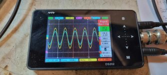
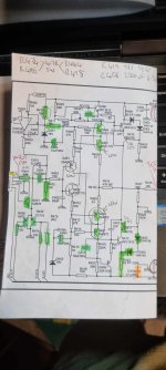
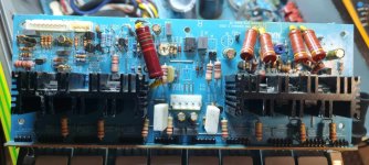
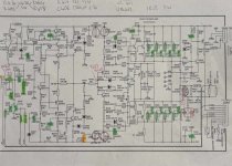
The photos show The input/VOP almost being the same on the scope, the full circuit diagram, the half that seems to be playing up and a photo of the PCB.
Many thanks,
Jamie.
I'm hoping the brains trust here can shed some light and help me restore this lump that I purchased new in 2006!
My old faithful (well, not so faithful) NAD C372 is giving me some grief.
Anyway, over the years it has had several issues, including me accidentally dropping a screwdriver in the case while it was running, which I repaired...In it's early days it was subject to a voltage fluctuation from an old generator set and was repaired by somebody else, but they also modified it to 'sound better. After I fix the issues I want to reverse those modifications and replace the notoriously bad capacitors. I have already replaced all the caps in the faulty amp module because I was gonna do it anyway...
The current issue appeared as no sound from the right channel. The Pre-amp stage on both channels worked fine, and transposing the L/R preamp signal worked on the good (L) channel. The input of the (R) amp module was attenuating/pulling the signal low. Removing Q429, 430 and 431 solved that issue for the moment, but the signal is not getting any gain before the output transistors.
Tracing through the good (L) amp module, I found the preamp signal gets amplified at Q410 and Q411. This is not happening on the (R) channel, I removed and tested Q411 and it tested fine in my TC1 tester. The only other thing I've noticed is the +/-68v rails appear to be 69v/73v...
I'm sure I've missed out a few details. but if anybody could look at the diagram and shed some light as I'm often puzzled by what things do, as there seems to be no explanations of the operation/block diagram.
The photos show The input/VOP almost being the same on the scope, the full circuit diagram, the half that seems to be playing up and a photo of the PCB.
Many thanks,
Jamie.
Attachments
Hi Jamie,
Welcome to the forum!
I've attached the full service manual, since some info is obscured in your jpg shots.
If I understand correctly, you have comparable probe connections on input and on VOP R terminals. In other words, the amp is showing abnormally low gain? Which trace is output?
The signals look clean, which is good news. Is output at VOP R showing 0VDC, i.e. no offset error? If so, also good news.
AC gain is set by R419//R422, R417,C406//C424. If you probe the junction of R417 with R419, the AC voltage should be about 3% of the AC voltage observed at VOP R. (This sets the AC gain of about 34.). There should be very little voltage at AC at C406; an open C406 might be the reason for low AC gain. The NB R should appear at junction of R408, R420.
Please advise if you find anything at odds with my description.
Good luck!
Steve
Attachments
Thank you Steve! Some of the sections of these amp circuits puzzle me...what the hell does that do?
The blue trace is the input pin of the amp module and the output pin is the speaker binding post. So there is gain, just SFA.
I will investigate tomorrow and report back.
The blue trace is the input pin of the amp module and the output pin is the speaker binding post. So there is gain, just SFA.
I will investigate tomorrow and report back.
I should mention that when I probe R428 the signal is low. But on the good (Left) amp module it is much higher (R328)
If you look at the diagram I uploaded, you can see where the amp was modified (I had some crazy old guy repair it when I couldn't stop it popping) and he insisted on modifying it.
You will see that he removed c406/c424 and replaced it with a pair of resistors in parallel, they measure 33ohms total.
He then removed R417 and R419 and put a 1k 5 watt resistor between the aforementioned 33 ohm resistor and the junction between R419/422.
He said it was to give it a 'More cass A sound'. I dunno. I think I want to return it to factory. What do you think?
Thanks.
Sorry for the successive posts,
As you asked I probed VOP R and got 0.496vac (when idle) and 1.042vac at R419/422. With a 500hz sine input both were about 0.475vac...
The voltage at NB R is 1.027vac...
So does that c406/c424/r419/r422 control the gain in the first stage of the module, via IC401A via the VOP input to IC401A?
Sorry for all the questions, there doesn't seem to be many resources explaining in a block diagram of the relationships of the sections and how they affect each other...you kinda just gotta know I guess!
Last edited:
Did one of the channels made loud continuous popping noise? As I'm facing loud popping noise in my C352. I have isolated it to the pre-amp section by removing the clips between pre and powerwhen I couldn't stop it popping)
Last edited:
SFA? I don't know that term. A gain of about 1.3 by my old eyes--- seem about right?
Did the crazy old guy change only the one channel? Is the other channel unchanged? Did he say how he cured the pop?
I'll follow up with more questions and a few details about about the design.
P.S. Did he make any changes other than those mentioned?
Did the crazy old guy change only the one channel? Is the other channel unchanged? Did he say how he cured the pop?
I'll follow up with more questions and a few details about about the design.
P.S. Did he make any changes other than those mentioned?
Last edited:

No popping. I just noticed one speaker wasn't doing much at all.Did one of the channels made loud continuous popping noise? As I'm facing loud popping noise in my C352. I have isolated it to the pre-amp section by removing the clips between pre and power
BSST: (for some reason I can't quote your posts).
SFA....sweet f**k all...not very much.
Both channels have been modified the same.
Sorry, bad terminology on my part, when I said popped, I meant the amp died. No audible popping. The problem at that time (almost 15 years ago) was the power supply which I repaired twice but it kept failing (damaged by generator fluctuations). Then he got excited and told me he could improve the amp...so I agreed. It's been running like that for all that time although some of the SMD caps in the preamp stage cracked so I replaced them, maybe 6 years ago.
He replaced R434/R444/R495/R496, but with standard values...maybe he fried them in me?
The only other thing I can see is he put another ceramic cap in parallel with c405 and c407...
I was concluding that he had probably revised both channels. I don't see anything wrong with his mods, Basically, he eliminated C406. Electrolytic caps have a bad rap in in that particular circuit spot. I'll try to explain details later. (BTW, are you familiar with the concept of Thevenin Equivalent circuits?)
His mod is theoretically sound, but he could have achieved the same result by simply shorting C406. The 5 Watt resistor may be a bit undersized. But it's likely to fail to a higher resistance that would raise gain rather than lower it.
None-the-less, I would carefully test the 33/(1k + 33) voltage divider. It has to present the correct attenuation ratio to produce the intended amp gain. Also confirm R417 value and path integrity back to R408,R406. If this network is not the culprit, we'll have to track down some other defect.
The servo opamp has low speed and sets the DC bias of the amp output to nominal 0V. Would you report the pin 1 voltage?
I'm traveling, so may be slow to respond for a couple of days.
Good luck!
Thanks BSST,
I don't know much about Thenevin equivalent circuits, I just had a read, so that's kind of what he (crazy ild guy) was trying to achieve?
So, one of his mods that I completely forgot, was to replace R417 with a 220uf cap. At some point I removed this to improve access to removing other components and forgot. I reinstalled it and...I was greeted with sound, enough to let the smoke out of my little test speaker...whoops!
So the original problem was dead IC401 and D401, which I replaced but forgot to replace the cap, so I was tearing my hair out.
I resoldered Q429/430/431 one by one and everything works fine. So the R channel is now ready for restoration and calibrating (the crazy old guy seemed to like rats nest style circuitry).
However, when I probed the left and right channels I noticed flattening of the sine wave every 180 degrees on the L channel. I traced that to the preamp...that should be easy.
Thank you so much for your help! Do you have paypal?
By the way, do you have a good resource for learning the theory behind amplifier design?
Thanks BSST.
Well. I'm an idiot. Since everything was working, I decided to restore everything back to the original circuit diagram. So c406, c424, r417, r419 and r422. I also removed the extra piggy back ceramic caps parallel with c405 and c407. Alas I didn't realise but there ended up being a tiny solder bridge between the junction of r 419/r422 (vop R) and 0VRB at R459.
It fired up and went straight into protect mode. So I powered down, studied the board and found the issue.
I fired it up again and it was all green lights. But the old attenuated input signal issue had returned. I removed the board and studied it. Then with the amp unplugged I plugged it back in but was a pin off with CZ404, which gave a small spark (capacitor still energised a bit?) This would have connected +64 on the pcb with 0vrb and 0vrb pn thr pcb with -64. No pops, no smoke.
Now 50% of the time it starts in protect mode.
I am beside myself. I could cry.
I checked the voltage on pin 1 of ic401a. I'm assuming the voltage is between pin 1 and pin 3 0vra? If so it's 18v! On the left channel it is 1.8v!I was concluding that he had probably revised both channels. I don't see anything wrong with his mods, Basically, he eliminated C406. Electrolytic caps have a bad rap in in that particular circuit spot. I'll try to explain details later. (BTW, are you familiar with the concept of Thevenin Equivalent circuits?)
His mod is theoretically sound, but he could have achieved the same result by simply shorting C406. The 5 Watt resistor may be a bit undersized. But it's likely to fail to a higher resistance that would raise gain rather than lower it.
None-the-less, I would carefully test the 33/(1k + 33) voltage divider. It has to present the correct attenuation ratio to produce the intended amp gain. Also confirm R417 value and path integrity back to R408,R406. If this network is not the culprit, we'll have to track down some other defect.
The servo opamp has low speed and sets the DC bias of the amp output to nominal 0V. Would you report the pin 1 voltage?
I'm traveling, so may be slow to respond for a couple of days.
Good luck!
I am close to the point of just ordering the whole pcb parts list and replacing everything now. I have no idea what damage I have done.
I would hold off on replacement boards. If the amp is operating half of time and making music, maybe it's close to workable.
I was just about to offer advice about servo but can't seem to locate some test points within the schematic.
Can you coach me where TP303 and TP304 are in schematic?
I was just about to offer advice about servo but can't seem to locate some test points within the schematic.
I. INITIAL ADJUSTMENT (No load connected)
A. OUTPUT OFFSET VOLTAGE
1. Connect a DC Millivoltmeter between TP303 and TP304, then adjust VR303
(50kohms) to get a reading of 0V +/-3V so at the speaker terminals of 0V+/-30mV.
2. Connect a DC Millivoltmeter between TP403 and TP404, then adjust VR401
(50kohms) to get a reading of 0V +/-3V so at the speaker terminals of 0V+/-30mV.
Can you coach me where TP303 and TP304 are in schematic?
Specifically, I'm trying to understand "(50kohms) to get a reading of 0V +/-3V so at the speaker terminals of 0V+/-30mV."
Don't curse yourself, it's happened to all of us at least once.Thanks BSST.
Well. I'm an idiot. Since everything was working, I decided to restore everything back to the original circuit diagram. So c406, c424, r417, r419 and r422. I also removed the extra piggy back ceramic caps parallel with c405 and c407. Alas I didn't realise but there ended up being a tiny solder bridge between the junction of r 419/r422 (vop R) and 0VRB at R459.
It fired up and went straight into protect mode. So I powered down, studied the board and found the issue.
I fired it up again and it was all green lights. But the old attenuated input signal issue had returned. I removed the board and studied it. Then with the amp unplugged I plugged it back in but was a pin off with CZ404, which gave a small spark (capacitor still energised a bit?) This would have connected +64 on the pcb with 0vrb and 0vrb pn thr pcb with -64. No pops, no smoke.
Now 50% of the time it starts in protect mode.
I am beside myself. I could cry.
Unfortunately (see my previous 2 posts) I've run into trouble and now have no sound out. The input signal is getting pulled right down to nothing. Trying to figure out where to go with this. Also trying to convince my partner that this is not going to be replaced with a sound bar 🙃I would hold off on replacement boards. If the amp is operating half of time and making music, maybe it's close to workable.
I was just about to offer advice about servo but can't seem to locate some test points within the schematic.
Can you coach me where TP303 and TP304 are in schematic?
- Home
- Amplifiers
- Solid State
- NAD C372....What a pest!