With reference to the attached paper by Hawksford (also uploaded by Hawksford here - https://www.researchgate.net/public...d_non-switching_power_amplifier_output_stages ).
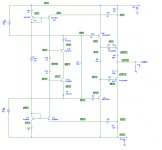
I thought I'd attempt to get an implementation working in spice - see attached png file. Note my implementation of the VCVS, I'd welcome any thoughts and constructive criticism.
Thanks,
Ian
I thought I'd attempt to get an implementation working in spice - see attached png file. Note my implementation of the VCVS, I'd welcome any thoughts and constructive criticism.
Thanks,
Ian
Attachments

Not sure that's a good idea, you're effectively changing the resistance of the current sense resistors in a non-linear fashion.
Mark, thanks for your suggestion, I may try adding Schottkys in the future.
In the meantime, I'm just posting the most basic circuits so we can collectively ascertain if it is useful or 'good enough'. I thought it was worth posting, because it is simpler than the majority of auto-bias circuits. The non-switching (or not) nature isn't really of interest to me.
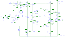
Hayk, I've simulated it with a standard blameless front end, see attached schematic png file, 40Vpk (80Vpk-pk) output into 4R. You can see the source resistor waveforms in the attached pdf.
As you can see, at 10kHz, the circuit has become non-non-switching! They look much better at 1kHz(also attached).
I don't think we should reject the circuit based on the fact it becomes non-non-switching at higher frequencies. In my humble opinion, the distortion is low enough at 10kHz :
FOURIER COMPONENTS OF TRANSIENT RESPONSE V(feed)
DC COMPONENT = -3.559496E-03
HARMONIC FREQUENCY FOURIER NORMALIZED PHASE NORMALIZED
NO (HZ) COMPONENT COMPONENT (DEG) PHASE (DEG)
1 1.000E+04 4.044E+01 1.000E+00 -5.607E-01 0.000E+00
2 2.000E+04 2.934E-04 7.254E-06 -1.567E+02 -1.562E+02
3 3.000E+04 4.212E-04 1.041E-05 -1.216E+02 -1.210E+02
4 4.000E+04 1.161E-04 2.872E-06 -1.002E+02 -9.963E+01
5 5.000E+04 5.034E-04 1.245E-05 -1.013E+02 -1.008E+02
6 6.000E+04 1.125E-04 2.782E-06 -1.633E+02 -1.627E+02
7 7.000E+04 3.297E-04 8.152E-06 -1.037E+02 -1.031E+02
8 8.000E+04 7.619E-05 1.884E-06 -1.479E+02 -1.473E+02
9 9.000E+04 4.340E-04 1.073E-05 -1.232E+02 -1.227E+02
10 1.000E+05 1.526E-04 3.773E-06 1.667E+02 1.672E+02
TOTAL HARMONIC DISTORTION = 2.305155E-03 PERCENT
Sadly, I don't use LTSpice, but I'm hopeful that somebody will perhaps redraw it in LTSpice and further develop it and/or add additional insight.
Thanks,
Ian
In the meantime, I'm just posting the most basic circuits so we can collectively ascertain if it is useful or 'good enough'. I thought it was worth posting, because it is simpler than the majority of auto-bias circuits. The non-switching (or not) nature isn't really of interest to me.
Hayk, I've simulated it with a standard blameless front end, see attached schematic png file, 40Vpk (80Vpk-pk) output into 4R. You can see the source resistor waveforms in the attached pdf.
As you can see, at 10kHz, the circuit has become non-non-switching! They look much better at 1kHz(also attached).
I don't think we should reject the circuit based on the fact it becomes non-non-switching at higher frequencies. In my humble opinion, the distortion is low enough at 10kHz :
FOURIER COMPONENTS OF TRANSIENT RESPONSE V(feed)
DC COMPONENT = -3.559496E-03
HARMONIC FREQUENCY FOURIER NORMALIZED PHASE NORMALIZED
NO (HZ) COMPONENT COMPONENT (DEG) PHASE (DEG)
1 1.000E+04 4.044E+01 1.000E+00 -5.607E-01 0.000E+00
2 2.000E+04 2.934E-04 7.254E-06 -1.567E+02 -1.562E+02
3 3.000E+04 4.212E-04 1.041E-05 -1.216E+02 -1.210E+02
4 4.000E+04 1.161E-04 2.872E-06 -1.002E+02 -9.963E+01
5 5.000E+04 5.034E-04 1.245E-05 -1.013E+02 -1.008E+02
6 6.000E+04 1.125E-04 2.782E-06 -1.633E+02 -1.627E+02
7 7.000E+04 3.297E-04 8.152E-06 -1.037E+02 -1.031E+02
8 8.000E+04 7.619E-05 1.884E-06 -1.479E+02 -1.473E+02
9 9.000E+04 4.340E-04 1.073E-05 -1.232E+02 -1.227E+02
10 1.000E+05 1.526E-04 3.773E-06 1.667E+02 1.672E+02
TOTAL HARMONIC DISTORTION = 2.305155E-03 PERCENT
Sadly, I don't use LTSpice, but I'm hopeful that somebody will perhaps redraw it in LTSpice and further develop it and/or add additional insight.
Thanks,
Ian
Attachments
H
HAYK
The purpose of non switching is to provide complimentary crossover transition up to highest frequency.

At 1khz the crossover is not complimentary, that is if one is fading in square law the other is waking up with the same square law so that when they cross, each has the half output impedance. Here is linear crossing.

At high frequency it is disaster.
At 1khz the crossover is not complimentary, that is if one is fading in square law the other is waking up with the same square law so that when they cross, each has the half output impedance. Here is linear crossing.
At high frequency it is disaster.
Hi Hayk,
I don't think Hawksford intended 'square law' operation, it doesn't feature in his paper.
Just because one of the transistors switches off (at higher frequencies), I don't think it should be declared a "disaster" (my opinion).
Cheers, Ian
I don't think Hawksford intended 'square law' operation, it doesn't feature in his paper.
Just because one of the transistors switches off (at higher frequencies), I don't think it should be declared a "disaster" (my opinion).
Cheers, Ian
Hi Hayk,
I don't think Hawksford intended 'square law' operation, it doesn't feature in his paper.
Just because one of the transistors switches off (at higher frequencies), I don't think it should be declared a "disaster" (my opinion).
Cheers, Ian
The square law operation is the central tenet of this paper!!
Hi Soundbloke,
It's certainly non-linear, but 'square' is a simplification, in much the same way that a simple diode demodulator is referred to as square.
It's certainly non-linear, but 'square' is a simplification, in much the same way that a simple diode demodulator is referred to as square.
Nonsense. The whole premise of the paper is utilising a modified linear Gilbert cell, and this is clearly explained in the paper.Hi Soundbloke,
It's certainly non-linear, but 'square' is a simplification, in much the same way that a simple diode demodulator is referred to as square.
It still produces a linear square law. The switching off is a result of the changed implementation in this thread, and I suggest that should have been made clearer.Ha, it's certainly modified!
Thanks for pointing out that the changed implementation causes the switch off. My sims suggest it is the addition of C43 that cause it. However, C43 is definitely needed for stability reasons (even with his original circuit and his component values).
Last edited:
Hi ihan,
Your deviations from Hawksford's Fig 3.2 implementation:

C43 across the bias generator is the main one. The bases of the two power transistors cannot be tied at HF with C34.
You have swapped the bias transistor polarities -- their two collectors are 'floating'.
They should have their two emitters connected -- forming a Rush pair.
The bases of the bias transistors are referenced to Vout (Feed) via the two resistors centre point.
The mirror transistors have small current sources -- but I'm not sure if this is essential for operation as I haven't sim'd it.
With luck😉, with these changes in your circuit, the bias loop will be stable and not need compensation (apart from the main feedback loop).
Your deviations from Hawksford's Fig 3.2 implementation:
C43 across the bias generator is the main one. The bases of the two power transistors cannot be tied at HF with C34.
You have swapped the bias transistor polarities -- their two collectors are 'floating'.
They should have their two emitters connected -- forming a Rush pair.
The bases of the bias transistors are referenced to Vout (Feed) via the two resistors centre point.
The mirror transistors have small current sources -- but I'm not sure if this is essential for operation as I haven't sim'd it.
With luck😉, with these changes in your circuit, the bias loop will be stable and not need compensation (apart from the main feedback loop).
- Home
- Amplifiers
- Solid State
- Hawksford non-switching autobias